Fender Rhodes Stage 88 · Volume 3
Fender Rhodes Stage 88 — Vol 03: Tools, Bench Setup & Teardown
This is the first volume of the refurbishment bench manual. It does two things: it lays out the toolkit and consumable stock a full Stage 88 refurbish wants on the bench before the first screw is turned, and it walks the factory disassembly sequence from Chapter Three of the Rhodes service manual in the exact order the manual prescribes — stand and pedal off, harp cover, nameboard, harp assembly, damper release bar, damper module, hammers, keyboard assembly, action rail and harp supports, then keys. The Stage 88 is an all-mechanical, passive instrument (Vol 02 §“The passive harp & wiring”): there are no live mains, no high-voltage rails, and no charged capacitors anywhere in a stock Stage, so the hazards here are mechanical — a cracked harp cover, a dropped keybed, a snapped tine — not electrical. The procedures that follow exist to avoid exactly those.
Note: This volume covers getting the piano apart and the parts safely stored. What to do with each sub-assembly once it is out lives in the volumes that follow: cabinet, tolex, legs, and the sustain pedal in Vol 04; tines, tonebars, grommets, and the tone-generator screw in Vol 05; key leveling, dip, escapement, dampers, and hammer tips in Vol 06; voicing in Vol 07; tuning in Vol 08. Reassembly is the teardown run in reverse, with the regulation passes of Vol 06–08 folded in.
3.1 The refurb toolkit
A Stage 88 is held together almost entirely by #2 Phillips wood screws and machine screws, with the tone-generator and tine hardware taking ¼″ and 5/16″ hex (fenderrhodes.com service manual, Chapter Three: Instructions for Disassembly; Chapter Six: Tine Replacement). The list below is the working bench kit; specialty regulation and voicing tools (the dip block, the black-key height tool, the long-shaft voicing driver) are called out where the matching procedure lives in later volumes.
Table 1 — The refurb toolkit
| Tool | Use | Where bought / spec |
|---|---|---|
| #2 Phillips screwdriver | Nameboard (4 screws), keybed-to-cabinet screws, most cabinet and rail hardware — the single most-used tool in the teardown | Any hardware store; a good hardened #2 tip (driver work is constant) |
| 6″ long-shaft #2 Phillips | Reaching the tone-bar / timbre screws and harp hardware down inside the harp without removing surrounding parts — used heavily in voicing (Vol 07) | Hardware store; a 6″+ shaft clears the tonebars |
| Small flat-blade screwdriver | Damper release-bar end screws; prying nylon bushings and clips; general | Hardware store; a 1/8″–3/16″ blade |
| ¼″ nut driver / wrench | Tine-screw and tone-generator hex hardware (Vol 05) | Hardware store; nut driver preferred for speed |
| 5/16″ nut driver / wrench | Tone-generator mounting hardware; tine-block nuts (Vol 05) | Hardware store |
| Side cutters (flush) | Cutting replacement tines to length against the chart (Vol 05 §“Tine replacement”) | Hardware store; sharp flush-cut |
| Bench vise | Clamping the tone generator so the factory power-torqued tine screw can be broken loose without bending the assembly (Vol 05) | Bench vise with soft jaws / jaw pads |
| Weighted key-dip block | Laying flat across the keys to read key dip (target 3/8″; Vol 06 §“Key dip”) | Avion Studios “Weighted Key Dip Block” (avionstudios.com); shop-made equivalents exist (Thingiverse) |
| Black-key height tool | Setting the sharps’ height relative to the naturals after the naturals are leveled (Vol 06 §“Key leveling”) | Avion Studios “Black Key Height Tool” (avionstudios.com) |
| Strobe tuner | Setting A=440 and tempering (Vol 08); verifying pitch after any tine bend during voicing (Vol 07) | Peterson strobe (StroboPlus / StroboClip) or iStroboSoft app (vintagevibe.com) |
| Heat gun | Softening old tolex adhesive for removal and re-laying new tolex (Vol 04 §“Re-tolexing”) | Hardware store; variable-temp preferred |
| Utility knife + steel straightedge | Trimming tolex; cutting the old covering off as a pattern (Vol 04) | Hardware store; fresh blades |
| Staple gun | Edge-stapling tolex at the case seams (Vol 04) | Hardware store; light-duty stapler |
| Contact cement | Bonding tolex to the case (Vol 04 §“The contact-cement debate”) | Neoprene contact cement or Vintage Vibe tolex glue (vintagevibe.com) |
| Sandpaper + tack cloth | Case surface prep before re-tolexing; lid refinishing (Vol 04) | Hardware store; assorted grits |
| Wood glue + filler + clamps | Case-joint and rear-panel structural repair (Vol 04 §“Case-joint repair”) | Hardware store; bar/pipe clamps sized to the case |
| Evapo-Rust (or equivalent) | De-rusting case corners, latches, harp hardware, leg hardware (Vol 04 §“Hardware”) | Evapo-Rust chelating bath (non-acid, reusable) |
| Soft-jaw pliers / nut drivers (leg hardware) | Removing legs, crossbars, and the center leg-brace knob (Vol 04) | Hardware store |
| Labeled parts bins + zip bags + marker | Sorting and bagging fasteners per sub-assembly (see §“Handling & storing parts”) | Any; the single biggest time-saver on reassembly |
| Camera / phone | Documenting every state before and during teardown (see §“Document everything first”) | Any phone camera |
Tip: Two of the regulation tools above (the weighted key-dip block and the black-key height tool) are sold by Avion Studios specifically for Rhodes work and are far more repeatable than eyeballing; the dip block is “tapered to lay flat on top of the keys” and reads a good average dip, and the black-key tool sets sharp height “in relation to the white keys” after the naturals are regulated (avionstudios.com). They earn their place on a bench that does more than one piano.
3.2 Consumables & replacement stock
A refurbish runs through stock parts and shop consumables. Ordering them before teardown means the piano is not sitting open on the bench for weeks waiting on a single grommet. Quantities depend on condition; the list is what a full Stage 88 refurbish typically draws on.
Table 2 — Consumables & replacement stock
| Item | What it is for | Source / note |
|---|---|---|
| Replacement tines (sized #1–#88) | Snapped or fatigued tines; tines break most often at the base (Vol 02 §“The asymmetric tuning fork”, Vol 05) | Vintage Vibe sells per-note tines; cut from blanks against the Ch.6 chart |
| Tonebar grommets | The rubber isolators under each tonebar; hardened grommets choke sustain and thin the tone (Vol 05 §“Grommets”) | Vintage Vibe / Tropical Fish grommet sets — replacement is “paramount to voicing” (vintagevibe.com) |
| Tuning springs | Lost or corroded bass-tine tuning springs (Vol 08) | Vintage Vibe |
| Hammer tips | Worn/hardened/grooved tips; graduated durometer set across the keyboard (Vol 06 §“Hammer tips”) | Vintage Vibe / Steve’s Corner; replace rather than over-shave |
| Key bushings / felts / punchings | Balance-rail and front-rail felt punchings for key leveling and dip shims (Vol 06) | Vintage Vibe; assorted thicknesses |
| Bridle straps | Damper-arm bridle straps, perished or torn (see teardown step 6) | Vintage Vibe |
| Sustain rod + guide cup | The original thin sustain guide cup “usually broke or went missing”; the rod seats in the guide cup, not the center hole (Vol 04) | Vintage Vibe / Custom Vintage Keyboards reinforced cup (vintagevibe.com; cvkeyboards.com) |
| Tolex kit | Re-covering the case; pre-cut kits reduce waste (Vol 04) | Vintage Vibe pre-cut tolex kit |
| Grill cloth (Suitcase only) | Speaker-cabinet grill recovering — not present on a Stage (Vol 04) | Vintage Vibe |
| Hardware — corners, latches, badges, screws | Replacing rusted/missing case and harp hardware (Vol 04) | Vintage Vibe / Tropical Fish |
| Contact cement / tolex glue, staples, sandpaper, tack cloth, wood glue, filler | Cabinet cosmetics consumables (Vol 04) | Hardware store / Vintage Vibe |
| Evapo-Rust bath | Reusable de-rust soak for hardware | Hardware store |
Note: Tine, grommet, hammer-tip, and tuning-spring specifications (tapers, durometer zones, per-note lengths) are not restated here — they belong to the procedures that consume them and are tabulated in Vol 05 (tone generator), Vol 06 (action), and Vol 08 (tuning). This section is the shopping list, not the spec sheet.
3.3 Document everything first
Nothing on a Stage 88 is captive-keyed: screws of similar length come out of a dozen sub-assemblies, the harp can be reinstalled fore-and-aft (which moves the strike line, Vol 06), and the action rail position sets key dip (Vol 06). A photographic and written record taken before anything moves is what makes reassembly a reversal rather than a guess.
- Photograph the assembled piano from every side, plus the underside of the open lid, before removing the harp cover. Capture the harp cover seated, the nameboard in place, and the leg/pedal arrangement.
- Photograph each layer as it is exposed, immediately before removing it — harp cover off, nameboard off, harp out, dampers out, hammers out. Each photo is the reference for putting that layer back.
- Record the as-found regulation state. Before disturbing anything, note (or photograph against a rule) the resting strike line position of the harp, the damper-arm rest position, and any obvious dead/buzzing notes, so the refurbish can be checked against — or deliberately improved on — the original.
- Bag and label fasteners by sub-assembly as they come out (see §“Handling & storing parts”). Do not pool screws.
- Note Stage-versus-Suitcase and Mark I-versus-Mark II details that affect reassembly — glides, cheek-block hardware, hammer-tip profile — at the moment they are observed.
Tip: The single most useful documentation habit is photographing each layer in place right before it comes off. A phone camera and a free hand are worth more on reassembly day than any written note.
3.4 Teardown sequence
The order below follows the service manual’s Chapter Three disassembly sequence (fenderrhodes.com, Chapter Three: Instructions for Disassembly; manualslib.com, Rhodes Piano Service Manual p.8). It is top-down: each step exposes the next. Tools are named per step. The exploded diagram that follows the steps numbers the same layers.
3.4.1 Exploded teardown order
3.4.2 Step 1 — Stand, crossbars & sustain pedal
Tools: #2 Phillips; leg-hardware nut driver/pliers.
- With the lid closed, stand the piano on its back or lay it flat per workspace, and remove the four legs, the crossbars/brace, and the center brace knob (cosmetic restoration of these is Vol 04 §“Legs/crossbars”).
- Remove the sustain pedal and rod. On reassembly the rod seats in the guide cup, not the center hole of the case — note this now (Vol 04 §“Sustain pedal”).
Note: The legs, crossbars, pedal, and rod are cabinet items; their de-rusting, repair, and the sustain-rod/guide-cup detail are handled in Vol 04. They come off first here only to free the case for the rest of the teardown.
3.4.3 Step 2 — Harp cover (lift the rear corners first)
Tools: hands only.
The harp cover is molded A.B.S. plastic and, per the manual, “practically impervious to damage” — if removed correctly. The manual’s method is exact: “Lift up on the two back corners of the molded top. With this done, simply pull the front edge free” (fenderrhodes.com, Chapter Three).
- Place both hands at the two rear corners of the cover and lift the rear edge up and free first.
- Once the rear is clear, pull the front edge free and lift the cover away.
Warn: Do not pry, lift, or force the harp cover from the front edge. The front edge is the molded lip that locates the cover; levering it up first concentrates stress there and cracks the ABS — the single most common avoidable damage in a Stage teardown. Always lift the rear corners first, then release the front (fenderrhodes.com, Chapter Three).
3.4.4 Step 3 — Nameboard (disconnect the harp cable first)
Tools: #2 Phillips.
- Disconnect the harp cable from the harp jack first. The nameboard carries the output jack and is tied to the harp by this cable; pulling the nameboard before unplugging it strains the cable and the harp wiring (fenderrhodes.com, Chapter Three).
- With a #2 Phillips, remove the four (4) screws mounting the nameboard to the cheek blocks. Two of the four are hidden behind the nameboard at each end (manualslib.com, Rhodes Piano Service Manual p.8).
- Lift the nameboard up and away.
Warn: Disconnect the harp cable before removing the nameboard screws. The harp’s passive output is a single, fragile fine-wire path (Vol 02 §“The passive harp & wiring”); yanking the nameboard with the cable still seated can tear the lead at the harp jack and turn a cosmetic job into a rewire.
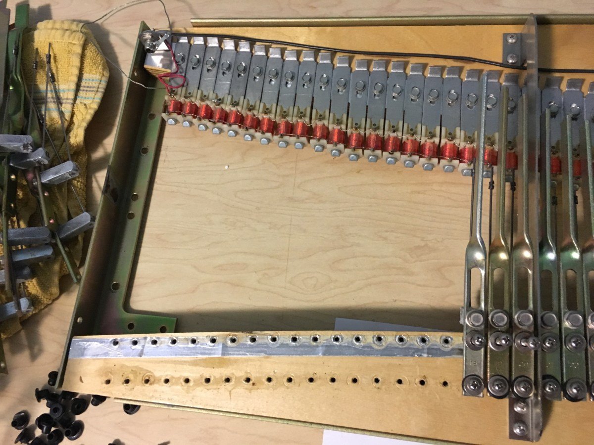
3.4.5 Step 4 — Harp assembly
Tools: #2 Phillips.
The harp assembly is three sub-assemblies — the harp frame, the tone-bar rail, and the pickup rail. The tone-bar rail and pickup rail are “seated into the Harp Frame and secured by fourteen (14) Mounting Screws” (fenderrhodes.com, Chapter Three). For teardown the whole harp lifts off as a unit:
- Remove the four (4) screws (two on each end) securing the harp to its aluminum harp supports.
- Remove the two (2) screws that secure the harp pivot links.
- Lift the harp assembly straight up and out. Detailed handling — and why the harp’s fore/aft position matters to the strike line — is in §“Harp removal & action access” below.
Warn: Lift the harp straight up and level. The tines are slender, fatigue-prone steel cantilevers that break most often at the base (Vol 02 §“The asymmetric tuning fork”); tilting or dragging the harp across the hammers or pickup rail can bend or snap a tine and scuff the pickup poles. Two hands, level, clear of the action.
3.4.6 Step 5 — Damper release bar
Tools: small flat-blade screwdriver.
- Loosen one screw on either end of the damper release bar.
- Slide the pivot pin out of the damper release bar through its nylon bushing, then slide the bar free of the other bushing (fenderrhodes.com, Chapter Three).
Note: The damper release bar is the cross-bar the sustain pedal drives to lift every damper at once. Damper regulation — rest firmness and lift height — is a Vol 06 procedure; here the bar simply comes out of the way.
3.4.7 Step 6 — Damper module
Tools: #2 Phillips.
- Remove the damper module mounting screws.
- Push down on each damper arm with one hand and gently pull the bridle strap forward to release it without tearing, then extract the module from the action rail (fenderrhodes.com, Chapter Three).
Warn: Ease each bridle strap forward by hand while holding the damper arm down. Pulling the module off without releasing the straps tears them; perished straps are a stock replacement item (see §“Consumables”), but needlessly tearing good ones adds work.
3.4.8 Step 7 — Hammers
Tools: fingers; #2 Phillips if removing a hammer comb/rail section.
Each hammer is retained by a protruding ear (pin) that snaps into the action rail. To free a hammer: “Hold the Hammer Head with the thumb and index finger then rotate either left or right while at the same time twisting on the vertical axis until the protruding ear (pin) pops out” (fenderrhodes.com, Chapter Three).
- Grip the hammer head between thumb and index finger.
- Rotate it left or right while twisting on its vertical axis until the ear pops free of the rail.
- Keep hammers in keyboard order as they come out (see §“Handling & storing parts”) — tip durometer is graduated across the keyboard (Vol 06 §“Hammer tips”).
Note: Hammer tips harden, groove, and are graduated by durometer from bass to treble; the Miracle Mod (a hammer-cam/pedestal bump, 1972–77) is also a hammer-area item. Both are Vol 06 topics. Here the hammers only come out — but keeping them in strict keyboard order makes the Vol 06 work far easier.
3.4.9 Step 8 — Keyboard assembly out of the case
Tools: #2 Phillips.
The whole keyboard assembly (keybed, keys, action rail, harp supports) lifts out of the cabinet as one unit. The Stage and Suitcase differ at this step.
- Position the piano so the keys point up with the bottom of the cabinet facing the technician (fenderrhodes.com, Chapter Three).
- Remove the two screws that secure the cabinet to the cheek-block cleat.
- Remove the two large screws that mount the keybed to the cabinet (#2 Phillips).
- Stage: lift the keyboard assembly out of the cabinet. Suitcase: also remove the four glides before lifting (fenderrhodes.com, Chapter Three).
Warn: Support the keybed with one hand to prevent it from falling out when the mounting screws are removed (fenderrhodes.com, Chapter Three). With the two large keybed screws out, nothing holds the assembly to the case; a dropped keybed bends tines, snaps hammers, and cracks keys.
3.4.10 Step 9 — Action rail & harp supports
Tools: #2 Phillips; nut driver or wrench (captive-washer nuts).
The service manual is explicit that the action rail is securely locked to both harp supports, and that maintaining them as a 3-piece assembly is recommended (fenderrhodes.com, Chapter Three). With the keyboard assembly out of the case (step 8), the action rail and harp supports come off the keybed together.
- Remove the captive-washer nuts from the keybed.
- Extract the action-rail mounting screws, protecting the T-nuts underneath the keybed from falling out.
- Lift the action rail + two harp supports away as one 3-piece assembly — do not separate the rail from the supports unless a specific repair requires it (fenderrhodes.com, Chapter Three).
Note: The action rail height is the key-dip adjustment. Key dip (factory 3/8″, Vol 06 §“Key dip”) is set by shimming the action rail, not by changing front-rail punchings — a point of frequent confusion. Disturbing the rail or its shims here means key dip must be re-checked on reassembly (Vol 06).
3.4.11 Step 10 — Cheek blocks & keys
Tools: #2 Phillips; fingers for the keys.
- Cheek blocks: remove the front and rear mounting screws and lift each cheek block off (fenderrhodes.com, Chapter Three).
- Keys: with the nameboard already off (step 3), lift up on the front of each key to free it from the front and center guide pins, then pull the key out from under the hammer (fenderrhodes.com, Chapter Three).
- Keep keys in strict keyboard order (see §“Handling & storing parts”).
Tip: Keys, like hammers, are nominally interchangeable but acquire wear patterns and bushing fit per slot. Removing and storing them in order keeps the action’s feel consistent on reassembly and isolates any one key’s fault to its own slot.
3.5 Harp removal & action access
The harp extraction in the sequence above (step 4) deserves its own treatment because it exposes the parts most refurbish work touches: lifting the harp off carries the entire tone generator and pickup rail away as a unit, clearing access to the action below.
3.5.1 The harp lifts off as a unit
The harp (step 4) carries everything that makes the note: the tine/tonebar forks, the tonebar rail, and the pickup rail with its 88 pickups (Vol 02 §“The passive harp & wiring”). Removing it as a unit gives clear bench access to the tines, tonebars, grommets, and pickups for the Vol 05 / Vol 07 work.
- Confirm the harp cable is disconnected (step 3) and the harp’s four support screws and two pivot-link screws are out (step 4).
- Note the harp’s fore/aft position against the case before lifting — the harp’s position sets the strike line (where each hammer meets its tine), which is graduated from roughly 2-1/4″ in the bass to about 1/8″ in the treble and is adjusted by sliding the harp (Vol 06 §“Strike line”). Photograph or mark it so the original strike line can be restored or deliberately improved.
- Lift the harp straight up, level, two hands, clear of the hammers and pickup rail.
- Set the harp on a padded surface, tines up, supported under the tonebar rail — never resting on the tines or pickups (see §“Handling & storing parts”).
Tip: The harp’s fore/aft seating is the strike line adjustment (Vol 06). Marking its as-found position before removal means reassembly starts from a known regulation point instead of an arbitrary one.
3.6 Handling & storing parts
A Stage 88 stripped to a bare keybed yields 88 keys, 88 hammers, the harp with 88 tine/tonebar forks, the damper module, and several bags of mixed fasteners. Disciplined storage is what keeps a multi-week refurbish from becoming a puzzle.
- Keep keys and hammers in keyboard order. Lay them in a long tray, slotted foam, or numbered slots, bass-to-treble. Hammer-tip durometer is graduated across the keyboard (Vol 06), so order is not cosmetic — it is functional.
- Store the harp tines-up, supported under the tonebar rail, on a padded surface or a dedicated harp cradle. Never rest the harp on its tines or pickups: the tines bend and the pickup poles scuff.
- Bag fasteners by sub-assembly, labeled. Nameboard screws, harp support screws, harp pivot-link screws, keybed screws, action-rail nuts, and cheek-block screws are similar but not interchangeable in length or count; pooling them guarantees a hunt on reassembly. One labeled bag per step of the teardown.
- Protect removed tonebars/grommets and pickups from oil, grit, and impact — they are the voicing-critical parts (Vol 05/07). Keep grommets out of heat and solvent, which harden them.
- Set aside cabinet items (legs, crossbars, pedal, rod, hardware) for the parallel Vol 04 cosmetic track — de-rusting and tolex work can proceed on the empty case while the action is on the bench.
Warn: Never stack parts on, or set the harp down on, the tines or pickups. A bent tine is a tuning and voicing fault (Vol 07/08) and a broken one is a replacement (Vol 05); a scuffed pickup pole changes that note’s output. The harp always rests tines-up, supported under the tonebar rail.
Tip: Reassembly is this sequence in reverse — keys, action rail/harp supports (as the 3-piece), keybed into case, hammers in order, damper module (re-seating each bridle strap), damper release bar, harp (to the marked strike line), nameboard (reconnect the harp cable), harp cover (front edge located, then rear corners down), then legs and pedal. The regulation, voicing, and tuning passes of Vol 06–08 are folded in as the action goes back together.
Sources
- fenderrhodes.com, Chapter Three: Instructions for Disassembly (Rhodes Keyboard Instruments factory service manual) — the full disassembly sequence and every quoted instruction: harp-cover rear-corner lift (“Lift up on the two back corners of the molded top … simply pull the front edge free”; ABS “practically impervious to damage”); nameboard removal (disconnect harp cable from harp jack; four #2 Phillips screws, two hidden at each end); harp assembly (harp frame + tone-bar rail + pickup rail; fourteen mounting screws; four support screws + two pivot-link screws); damper release bar (loosen one screw each end; slide pivot pin out through the nylon bushing); damper module (push damper arm down, ease bridle strap forward); hammer removal (rotate and twist the head until the ear/pin pops out); keyboard-assembly removal (keys up, cabinet bottom facing the tech; two cheek-block cleat screws + two large keybed screws; Suitcase also removes four glides; “support the keybed … to prevent the keybed from falling out”); action rail + harp supports as a locked 3-piece assembly with captive-washer nuts and T-nuts; cheek-block front/rear screws; and key removal (lift the front off the guide pins, draw out from under the hammer).
- manualslib.com, Rhodes Piano Service Manual p.8 (Chapter 3) — corroborating scan of the harp-cover, nameboard, and harp-assembly steps, including the four-screw nameboard count with two screws hidden behind each end.
- avionstudios.com — Weighted Key Dip Block (“tapered to lay flat on top of the keys,” reads a good average key dip) and Black Key Height Tool (sets sharp height in relation to the white keys, after the naturals are regulated): the two Rhodes-specific regulation gauges on the toolkit list.
- vintagevibe.com — Fender Rhodes parts (tines, tonebar grommets — replacement “paramount to voicing”, hammer tips, bridle straps, tuning springs, sustain rod + reinforced guide cup, tolex kits, hardware) for the consumables/replacement-stock list; the sustain rod seats in the guide cup, not the center hole.
- cvkeyboards.com (Custom Vintage Keyboards) — reinforced sustain guide cup (the original thin cup “usually broke or went missing”), corroborating the guide-cup-not-center-hole reassembly note.
- Cross-references: cabinet, tolex, legs, crossbars, hardware, and the sustain pedal/rod/guide-cup in Vol 04; tines, tonebars, grommets, and the tone-generator screw (vise-clamped, ¼″ + 5/16″ hex) in Vol 05; key leveling, key dip (action-rail shim), escapement, strike line, damper regulation, hammer tips, and the Miracle Mod in Vol 06; voicing and tine-to-pickup alignment (the 6″ long-shaft driver) in Vol 07; tuning, the tuning spring, and the strobe method in Vol 08. The passive harp, tine/tonebar fork, and signal path are Vol 02.
No torque values, screw counts, or dimensions have been invented; screw counts and the disassembly order are quoted from the service manual’s Chapter Three, and regulation dimensions referenced in passing (key dip 3/8″, strike line ~2-1/4″→1/8″) are carried with their Vol 06 citation and developed there. Tool brands are named where a specific Rhodes-purpose product exists (Avion dip block / black-key tool; Vintage Vibe parts and tolex; Peterson / iStroboSoft strobe); generic tools are left to the technician’s preferred supplier.
Comments (0)