Hammond B-3 · Volume 6
Hammond B-3 — Vol 06: Maintenance & Restoration
This volume is the bench-grade service and restoration reference for the B-3 console, its scanner-vibrato assembly, and the Leslie 122 cabinet. It treats the rig as the electromechanical reality it is: a synchronous-motor-driven tonewheel generator that must be oiled through a capillary wicking system, hundreds of precious-metal key contacts that oxidise, decades-old electrolytic capacitors that dry out and leak, and a tube power amplifier carrying lethal high-voltage rails. Theory of operation is Vol 02; the Leslie’s internal anatomy and its high-voltage supply are Vol 04; controls and the scanner as a musical device are Vol 03. This volume does not re-derive any of that — it documents how to keep the machine alive without damaging it or the technician.
Warn: This is a SAFETY-CRITICAL volume. The B-3 console, the AO-28 output amplifier, and the Leslie 122 amplifier are all connected directly to the AC mains and develop high-voltage B+ rails (the Leslie amp on the order of +400 V to +430 VDC; ~+415 VDC at the 6550A plates — Vol 04 §“The amplifier & power supply”) that persist on filter capacitors after power-off and after the cord is pulled. Older consoles and Leslies also carry an AC line-to-chassis “death cap” that can put mains voltage on the chassis when it fails. No internal electrical work may be done live. The consolidated hazard list and the capacitor-discharge procedure are in §“Safety” — read it before opening any chassis.
Routine: lubrication
The Hammond tonewheel generator, the synchronous motor, the vibrato scanner, and the Leslie rotor motors are all oil-lubricated through capillary action, not packed with grease. Oil placed in a cup or funnel is drawn along cotton wicking threads (strings) to each bearing and spindle. This is the single most important maintenance fact about the instrument, and it dictates exactly which oil may be used.
Why only Hammond oil
The generator uses a capillary oiling system, and Hammond organ oil is “specifically formulated to work in this environment” — a low-viscosity, non-detergent mineral oil thin enough to travel the cotton thread to the bearing (Benton Electronics, “Oiling Instructions for the Hammond Organ,” bentonelectronics.com; Hammond Organ Co., hammondorganco.com/oils). The wrong oil does not merely under-lubricate; it actively destroys the system:
- Detergent motor oils and multigrade oils leave deposits and, with the detergent package, attack the wicking. “Some oil substitutes will definitely clog the organ’s cotton oiling threads and create a major service issue” (organforum.com; dairiki.org HammondWiki, “Oiling The Hammond”).
- 3-in-1 oil and most household oils are too heavy and/or gum over time; once a thread is gummed it stops wicking and the bearing it feeds runs dry — typically heard later as a squealing tonewheel bearing (narkive alt.music.hammond-organ, “squealing tonewheel bearing — no oiling thread”).
The correct product is sold today as Hammond tonewheel-generator oil / “Leslie oil” by Hammond and the restoration trade (hammondorganco.com/oils; tonewheelgeneral.com; goffprof.com).
Warn: Never substitute 3-in-1, sewing-machine household oil, automotive motor oil, or any detergent/multigrade oil in the tonewheel generator. The wrong oil gums the cotton wicking threads, after which the affected bearings run dry regardless of how much oil is later added — a major teardown to correct. Use only Hammond-branded organ/tonewheel oil.
The oiling points and how much
A two-switch console (B-3, C-3, A-100) has oiling points on the generator, on the run/start motor + scanner assembly, and (on some chassis) a pair of upper oil cups. Quantities below follow the Benton Electronics instruction sheet for two-switch consoles (bentonelectronics.com); fill levels matter because over-oiling is as damaging as under-oiling — excess oil migrates onto the scanner plates and key contacts.
| Point | Location | How much (annual) | Source |
|---|---|---|---|
| Tone-generator funnels | Two funnels on the generator | Fill twice each (a funnel-full, let it drain, repeat) | bentonelectronics.com |
| Motor / scanner tub | Left-rear felt tub | Only moisten the felt — do not flood | bentonelectronics.com |
| Upper oil cups (where fitted) | Left = motor, right = generator | Left cup half-full; right cup to the top | bentonelectronics.com |
| Scanner bearing | Under the motor/scanner tub felt | One very small drop on the shaft bearing when the tub is serviced | bentonelectronics.com |
Exact drop-counts beyond the above are not specified in the period literature and are (est.) where a technician interpolates; the governing rule is “a small amount in each point, once a year, and let capillary action do the rest.” After oiling, the oil “will take a week or more to get to all the bearings” (bentonelectronics.com), so a freshly oiled organ should not be judged dry the same day.
Interval
The published interval is once per year under normal use (“normal annual oiling”; bentonelectronics.com). An organ that has gone longer than a year, or whose history is unknown, should be given an additional catch-up dose and then returned to the annual schedule (bentonelectronics.com; dairiki.org “Oiling The Hammond”).
| Assembly | Interval | Consumable / spec |
|---|---|---|
| Tonewheel generator | Annually (catch-up dose if overdue) | Hammond tonewheel-generator oil (low-viscosity, non-detergent mineral oil) |
| Run/start motor + scanner | Annually | Same Hammond oil; felt only moistened |
| Leslie 122 rotor motors | Annually | Leslie oil, or a light non-detergent machine oil (e.g. sewing-machine oil) into the felt-pad reservoirs — sparingly (bentonelectronics.com, “Servicing the Leslie Motors”) |
Note: The Leslie motors are the one place the trade tolerates a substitute — Benton notes that if Leslie oil is unavailable, “a good small motor oil like sewing machine oil” is acceptable because the Leslie motor bearings use a felt-pad reservoir rather than the console’s long cotton wicks (bentonelectronics.com). This tolerance does not extend to the Hammond generator, which must have Hammond oil.
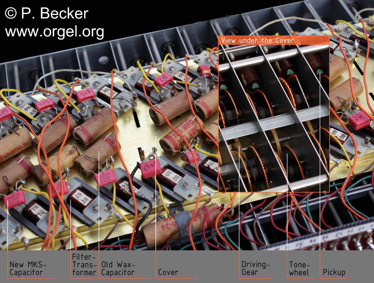
The generator oiling / wicking system
Capacitors: reforming, recapping & the death cap
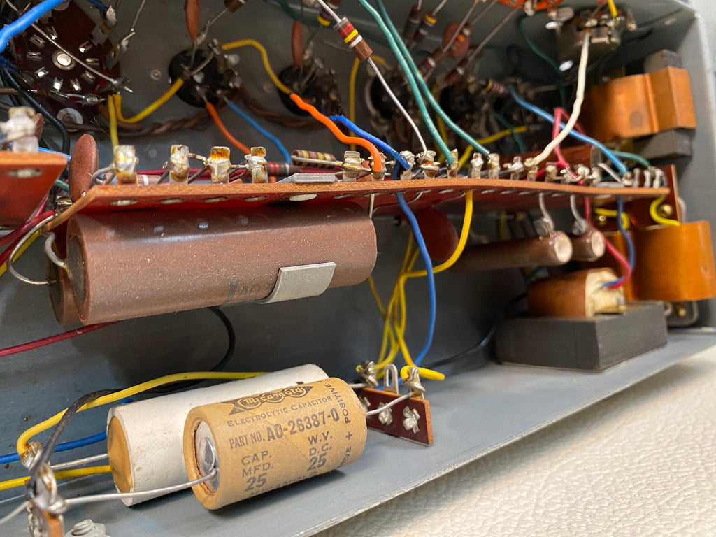
Every electrolytic capacitor in the rig is decades old. Aluminium electrolytics dry out, lose capacitance, develop high ESR, and leak — the audible and electrical symptoms are mains hum, sagging or drifting B+ rails, bias drift in the tube stages, and weak or distorted output. Three capacitor populations matter: the B-3 console power supply and AO-28 preamp electrolytics, the vibrato line-box components, and the Leslie 122 amplifier electrolytics. A fourth item — the AC line-to-chassis “death cap” — is not a performance part at all but a safety defect.
Reforming vs. replacing
An electrolytic that has sat unpowered for years should never be slammed with full B+ cold. Two valid approaches:
- Reforming — bringing the rail up slowly (via a variac or a current-limited bench supply) so the capacitor can rebuild its oxide dielectric without a destructive surge. This can recover a marginal cap and is the standard first move when first powering a long-dormant organ or Leslie.
- Replacement (recapping) — fitting new electrolytics of the correct capacitance (µF) and equal-or-higher working voltage (WVDC). In the Leslie 122 the key parts are the multi-section filter capacitor in the high-voltage supply and the coupling capacitors between stages; Benton specifically calls out the four-section filter capacitor and notes that the CDE “green” coupling caps between the 12AU7A and the 6550A pair are known to fail (bentonelectronics.com, “Servicing the Leslie 122 Amplifier”). On the console side, the AO-28 and power-supply electrolytics are the recap targets that cure persistent hum and bias drift.
Warn: Power-supply and Leslie-amp filter capacitors store a lethal charge at +400 V to +430 VDC and hold it for a long time after the equipment is switched off and unplugged (Vol 04 §“The amplifier & power supply”). Before touching, unsoldering, or testing any capacitor in these supplies, the rail must be discharged and then verified at 0 V with a meter — see §“Safety.” Replacement electrolytics must be rated at equal or higher working voltage than the originals; never fit an under-rated cap into an HV rail.
Note: Capacitance is specified in µF and the working voltage in WVDC; both are printed on the original and must be matched (capacitance exactly, voltage equal-or-higher). Specific µF/WVDC values are chassis-revision dependent and are read off the part or the unit’s own schematic — they are not restated here as invented numbers.
The AC “death cap”
Older Hammond consoles and Leslie cabinets were built with a capacitor wired from one side of the AC line to the chassis (the “death cap”), originally fitted for RF/hum suppression on two-wire, non-polarised mains. Typical values are small — on the order of 0.047 µF to 0.1 µF (HammondWiki “Death Caps,” dairiki.org; KR Sound, kr-sound.com). The defect is in how it fails: these old paper/wax/mica/film parts fail short, and “then you have Mains AC directly connected to chassis” (dairiki.org, quoting the failure mode) — putting full line voltage on every exposed metal surface of the instrument.
The correct restoration fix is unambiguous:
- Remove the death cap entirely, and
- Fit a proper grounded three-wire (earthed) power cord, bonding the chassis to mains earth so a fault trips the breaker instead of energising the chassis (dairiki.org; KR Sound).
- Where a line-to-chassis capacitor is genuinely wanted for RF suppression, use only a safety-rated Y-class capacitor (Y2, carrying UL1414 / EN60950-type approval), which is constructed to fail open, not short (dairiki.org). A standard film or electrolytic cap is never acceptable in that position.
Warn: The AC “death cap” is a direct electrocution hazard. On any pre-grounded-cord Hammond console or Leslie, remove the line-to-chassis death cap and install a grounded three-wire cord before the instrument is returned to service. Do not simply replace the old cap with another non-safety part. Only a Y-rated safety capacitor may occupy a line-to-chassis position, and only alongside a proper earth. A failed death cap can put full mains voltage on the chassis, keybed hardware, and pedal contacts.
Key contacts & the “Hammond fix”
Each playing key actuates nine separate contacts — one per drawbar harmonic — wiping against nine busbars per manual (one busbar per drawbar) (forums.musicplayer.com, “Hammond 9 Key Contacts Assigned to Harmonics”; b3world.com). These are precious-metal wire contacts wiping a lubricated busbar. Over decades the contact points oxidise and collect dust, which raises contact resistance and produces the classic symptoms: dead or weak individual harmonics, intermittent notes, and crackle that changes as the key is worked.
The fix is graduated, least-invasive first — the well-known “Hammond fix”:
- Exercise the keys. “Dirty contacts can be cleaned up by playing the offending notes harder than normal” — strike each offending key firmly ~20 times to let the wiping action abrade through the oxide (dairiki.org, “How To Clean Key Contacts”). This alone clears most intermittent notes.
- Shift the busbar. For stubborn contacts, turn the manual’s busbar shifter about two turns in either direction, which moves every contact to a fresh, un-oxidised spot on the busbar and dislodges accumulated dust (dairiki.org).
- Clean the busbar (last resort). Only if the above fail: remove each busbar, clean it with a mild residue-free solvent (denatured or isopropyl alcohol — trade practice), and refit. This is delicate work best left to an experienced technician; adjusting the busbar shifters with keys depressed is itself “pretty risky business” (dairiki.org).
Warn: Do not use abrasives (files, abrasive pads, eraser grit) or harsh/aggressive solvents on the key contacts or busbars. The busbars carry a specific lubricant; abrasives remove the precious-metal plating and harsh solvents strip the lubricant, turning an intermittent note into a permanently damaged contact. Use only the graduated Hammond-fix steps and, at most, denatured alcohol on a removed busbar.
Note: Because the key wiring and busbars are not directly across the mains, the key-contact procedures themselves are low-voltage. The hazard during this work is reaching past the contacts into the live power supply / AO-28 area of the console — keep the organ unplugged and the supply discharged whenever the underside is open.
Drawbars & the vibrato scanner
Drawbar contacts
The drawbars are multi-tap sliding contacts; like the key contacts they oxidise and grow intermittent, producing scratchy or stepped level changes as a drawbar is moved. They respond to the same philosophy: work them through their travel to wipe the contacts clean, and where cleaning is needed use a contact cleaner safe for precious-metal contacts, applied sparingly — not an abrasive and not a residue-leaving aerosol that will attack the contact lubricant.
The vibrato scanner
The scanner is a small rotary air-gap variable capacitor — a rotor sweeping past a ring of 16 fixed capacitor plates, each tapped off the vibrato delay (line-box) — that produces the phase-swept vibrato/chorus (mechanism and musical role: Vol 03 §3.4). Two failure modes dominate, and both are service items here:
- Oil contamination of the plates. The scanner sits next to an oiled motor; over-oiling migrates onto the fibre insulating washers and plates, where it can short the signal to ground and make the vibrato weak or erratic. Moist-looking insulators “may be shorting the signal to ground and will need cleaning” (bentonelectronics.com, “Servicing the Hammond Vibrato Scanner”). This is the practical reason the motor/scanner felt tub is only moistened, never flooded (§“Routine: lubrication”).
- Scanner bearing lubrication. When the scanner/motor tub is serviced, the felt and wicking strings are removed with great care and a single very small drop of Hammond oil is placed on the shaft bearing (bentonelectronics.com).
Warn: The vibrato scanner shares the console chassis with the AC mains supply and the AO-28’s high-voltage rails. Clean or oil the scanner only with the organ unplugged and the power supply discharged; do not service it on a live console.
The vibrato line box
The line box is the LC delay line the scanner samples. Its original critical-value capacitors and resistors drift and fail with age, producing “random variations in vibrato and chorus performance” (bentonelectronics.com, “Servicing the Hammond Vibrato Scanner”). A proper line-box rebuild is a complete replacement of the original capacitors and resistors with correct values — a recap, treated the same way as the power-supply electrolytics but at signal level.
Leslie 122 service
The Leslie 122 has three independent service domains: the drive belts, the rotor motors, and the tube amplifier. Cabinet anatomy, rotor speeds, the 6-pin balanced connection, and the amplifier’s tube complement are Vol 04 — this section is the maintenance overlay.
Belts
The horn and drum are belt-driven, and the rubber/polyurethane belts perish, stretch, glaze, and crack with age, causing slow run-up, speed instability, or a rotor that will not turn. The 122/147 uses two distinct belts:
| Belt | Drives | Length | Material | Source |
|---|---|---|---|---|
| Upper drive | Treble horn rotor | ~25.5 in | Rubber (chemical/abrasion resistant) | amplifiedparts.com; tonewheelgeneral.com |
| Lower drive | Bass drum rotor | ~31 in | Polyurethane | amplifiedparts.com; tonewheelgeneral.com |
Belts are a routine replacement on any unserviced cabinet; a glazed or perished belt is the most common cause of a Leslie that “won’t speed up.”
Motors
Each rotor has a fast and a slow motor stack (Vol 04 §“Fast/slow”). The motor bearings use a felt-pad oil reservoir and need little oil, at roughly yearly intervals; Leslie oil is correct, and a light non-detergent machine oil such as sewing-machine oil is the accepted substitute (bentonelectronics.com, “Servicing the Leslie Motors”). Over-oiling throws oil onto the rotor and belts — apply sparingly, only enough to wet the felt.
Warn: Do not over-oil the Leslie motors. Each felt pad absorbs only a limited amount; excess oil is flung onto the belts and rotor, glazing the belt (slip) and contaminating bearings. Oil sparingly, annually.
Amplifier: recap + retube + connectors
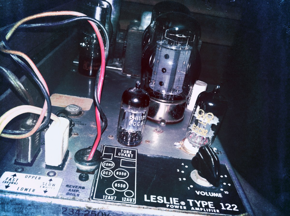
The 122 amplifier is a tube power amp running B+ ≈ +415 VDC at the 6550A plates (Vol 04 §“The amplifier & power supply”). A full restoration is:
- Recap — replace the multi-section filter capacitor in the HV supply and the ageing coupling capacitors between the 12AU7A driver and the 6550A pair (Benton specifically flags the .0047 µF / 1600 V feedback cap, pin 3–5 via a 390 kΩ resistor, as a known leaker); always verify the 6550 cathode resistor and its bypass capacitor (bentonelectronics.com). The molded “green” CDE coupling caps are a widely-reported failure item in the trade.
- Retube — replace the 6550A output pair as a matched set from a reputable supplier, and the 12AU7A balanced driver; rebias as required after fitting (bentonelectronics.com; organforum.com).
- Connectors / relay — clean the 6-pin connector contacts and the internal speed-changeover relay contacts; dirty contacts here cause intermittent audio, no audio on one leg, or a speed that will not switch. The 6-pin cable carries AC mains and a high-voltage DC feed alongside the audio (Vol 04 §“The 6-pin balanced connection”).
Warn: The Leslie 122 amplifier develops B+ on the order of +400 V to +430 VDC, and its filter capacitors hold a lethal charge after power-off and after the cabinet is unplugged (Vol 04 §“The amplifier & power supply”). Discharge and verify before any recap/retube/connector work. The tubes also run physically hot — allow cool-down before handling the 6550A pair. Never mate or de-mate the 6-pin connector live: it carries mains and HV DC, not just audio.
Common faults → fixes
| Fault | Symptom | Likely cause | Fix |
|---|---|---|---|
| Dead / weak single harmonic | One drawbar’s note missing or faint on a key | Oxidised key contact for that harmonic | Hammond fix: strike key firmly ~20×; then busbar shifter ~2 turns (dairiki.org) |
| Intermittent / crackly note | Note drops out or crackles when key is worked | Dirty key contact / busbar dust | Exercise keys; busbar shift; last resort clean busbar with denatured alcohol (dairiki.org) |
| Scratchy drawbar | Stepped/noisy level as drawbar moves | Oxidised drawbar contacts | Work drawbar through travel; precious-metal-safe contact cleaner, sparingly |
| Squealing / rumbling tonewheel | High-pitched squeal or growl from generator | Bearing run dry — gummed or starved wick | Correct Hammond oil; if wick gummed by wrong oil, replace wick (organforum.com; narkive) |
| Mains hum from console/Leslie | Steady 60 Hz / 120 Hz hum | Dried/leaky power-supply electrolytics | Reform, then recap power-supply/AO-28/Leslie filter caps |
| Weak vibrato/chorus, erratic | Vibrato shallow, uneven, or noisy | Oil on scanner plates; or drifted line-box parts | Clean scanner insulators; rebuild (recap) the line box (bentonelectronics.com) |
| Leslie won’t speed up / unstable | Rotor slow to run up, wrong speed, or won’t turn | Perished/glazed/slipping drive belt | Replace upper (~25.5 in) and/or lower (~31 in) belt (amplifiedparts.com) |
| Leslie distorted / weak / no output | Low output, distortion, or dead channel | Failed coupling/filter caps; worn 6550A pair | Recap (filter + coupling caps, incl. the .0047 µF/1600 V feedback cap); retube 6550A as matched pair + 12AU7A (bentonelectronics.com) |
| Leslie won’t change speed | Stuck on one speed | Dirty changeover relay / 6-pin connector | Clean relay and 6-pin contacts (de-energised) |
| Hot chassis / shock on touch | Tingle or shock from metal parts | Failed AC line-to-chassis death cap | Remove death cap; fit grounded 3-wire cord (dairiki.org) — see §“Safety” |
Safety
Every electrical hazard in this rig is collected here as an explicit callout. Nothing in this section is optional.
Warn: MAINS. The B-3 console, the AO-28, and the Leslie 122 connect directly to the AC line. Unplug the equipment before opening any chassis. On any pre-grounded-cord unit, treat the chassis as potentially live until the death cap is removed and a grounded three-wire cord is fitted (dairiki.org).
Warn: DEATH CAP. A failed AC line-to-chassis capacitor (~0.047–0.1 µF) can connect full mains voltage to the chassis, keybed, and pedal hardware. Remove it and earth the chassis with a three-wire cord; if RF suppression is wanted, use only a Y2 safety-rated capacitor that fails open (dairiki.org; kr-sound.com).
Warn: HIGH-VOLTAGE B+. The AO-28 and especially the Leslie 122 amplifier carry B+ rails on the order of +400 V to +430 VDC (~+415 VDC at the 6550A plates) (Vol 04 §“The amplifier & power supply”). These rails are stored on the filter capacitors and persist after power-off and after the cord is pulled. Assume every filter cap is charged until proven otherwise.
Warn: TUBE HEAT. The 6550A and 12AU7A run hot enough to burn. Allow the Leslie amplifier to cool before handling tubes; do not touch glass envelopes during or immediately after operation.
Warn: THE 6-PIN LESLIE CABLE carries AC mains and a high-voltage DC feed alongside the balanced audio (Vol 04 §“The 6-pin balanced connection”). Mate and de-mate it only with the whole system powered down. Never probe or hot-plug it.
Capacitor-discharge procedure (general)
The following is the general bench procedure for the HV supplies. It is stated in general terms — exact test points are read from the unit’s own schematic.
- Power off and unplug the console or Leslie. Wait — but do not assume time alone has bled the rail.
- Set a DMM to a high DC-volts range and measure across the main filter capacitor / B+ rail to confirm whether a charge remains.
- If a charge is present, discharge it through a suitable high-wattage bleeder resistor (a resistor in series with the meter/clip lead, not a bare screwdriver — a dead short can damage components and spray molten metal) across the capacitor terminals, observing the voltage fall toward 0 V.
- Re-measure and confirm 0 V at every section of a multi-section filter cap before any soldering, unclipping, or hand contact. A multi-section can hold charge on a section the bleeder missed.
- Keep one hand clear, work on an insulated surface, and re-verify after any pause — capacitors can recover a surface charge (“dielectric soak”) after an initial discharge.
Warn: Never discharge an HV filter capacitor by shorting it with a bare screwdriver. Use a resistor-limited discharge tool, then verify 0 V with a meter at every capacitor section before touching the circuit. The B+ in these supplies is lethal; treat “unplugged” as “still charged” until the meter reads zero.
Sources consulted: “Oiling Instructions for the Hammond Organ,” “Servicing the Leslie 122 Amplifier,” “Servicing the Leslie Motors,” and “Servicing the Hammond Vibrato Scanner” — bentonelectronics.com; Hammond Organ Co. oils — hammondorganco.com/oils; Tonewheel General Hospital — tonewheelgeneral.com; GOFF Professional — goffprof.com; HammondWiki “Oiling The Hammond,” “Death Caps,” and “How To Clean Key Contacts” — dairiki.org; The Organ Forum (organforum.com) on tonewheel oil and 6550 replacement; “Hammond 9 Key Contacts Assigned to Harmonics” — forums.musicplayer.com; b3world.com Hammond maintenance; KR Sound death-cap article — kr-sound.com; Leslie belt specifications — amplifiedparts.com; alt.music.hammond-organ (narkive) on dry tonewheel bearings. Quantities and intervals are quoted from the cited service sheets; values that could not be pinned to a single authoritative figure are marked “(est.).” No torque, voltage, oil-quantity, or capacitor value has been invented; HV figures are carried with citation from Vol 04. Cross-references: Vol 02 (theory of operation), Vol 03 §3.4 (scanner/vibrato as a control), Vol 04 (Leslie 122 anatomy and high-voltage supply).