Hammond B-3 · Volume 2
Hammond B-3 — Vol 02: Theory of Operation & Signal Path
This volume traces the B-3 from rotating iron to line output: how a synchronous motor derives pitch from the AC mains, how 96 tonewheels (91 of them active) turn that rotation into near-sinusoidal voltages, how nine drawbars sum those voltages into additive timbres, how nine key contacts per key gate the bus, why foldback lets 91 wheels cover both manuals, and how the matching transformer and AO-28 preamp hand a balanced line signal to the Leslie. Wheel counts here match Vol 01 §“Spotting a genuine console”: 96 tonewheels total, 91 active. Mechanical and amplifier specifics referenced in Vol 01 §2 are developed here.
Note: Electrical and mechanical figures in this volume are stated with units and polarity, and every spec is cited inline. Where a value could not be confirmed from the consulted sources it is marked (est.) or explicitly flagged as unconfirmed and deferred — no electrical value is invented.
2.1 Block diagram
The B-3 is a strictly serial chain from mains-locked rotation to a balanced line feed. The synchronous motor sets the master speed; the tonewheel generator turns that speed into voltages; the key contacts gate them onto nine footage busbars; the drawbars tap a matching transformer to set each harmonic’s level; the AO-28 preamp buffers and voices the summed bus; the 6-pin connector carries the result to the Leslie (Hammond B-3/C-3 Service Manual; electricdruid.net, Technical aspects of the Hammond Organ).
Tip: The chain is unbranched up to the drawbars. That is why a single dirty key contact or a single weak wheel is audible as one specific note or one specific harmonic — there is no redundancy to hide behind.
2.2 The synchronous motor & start/run
The generator shaft is turned by two motors working in sequence, a consequence of the run motor’s defining property: a synchronous AC motor locks its rotation to the mains frequency but cannot start itself from rest (bentonelectronics.com, Hammond Synchronous Run Motor and Hammond Generator Start Motor).
-
Run motor (synchronous). A non-self-starting synchronous motor whose rotation is phase-locked to the AC line. On 60 Hz mains the shaft turns at 1200 RPM (20 rev/s); on 50 Hz mains it turns at 1500 RPM — note that the higher number-of-RPM here corresponds to the lower mains frequency only because the pole count differs, and either way the generator pitch is derived directly from the mains (bentonelectronics.com; dairiki.org GearRatio). The two field coils measure roughly 180 Ω each; with both coils wired in parallel the combined resistance reads approximately 90 Ω — a useful bench diagnostic: a reading of ~180 Ω across the parallel motor terminals indicates one open coil; an open circuit indicates both have failed (bentonelectronics.com, Hammond Synchronous Run Motor). The run motor delivers two torque pulses per AC cycle — 120 pulses/s on 60 Hz mains — which is the mechanical mechanism by which the line frequency enforces pitch; the output torque is pulsed, not constant (bentonelectronics.com). Because pitch follows the mains, a B-3 fed by a frequency-accurate supply holds tune indefinitely, and a B-3 run on an out-of-spec inverter plays sharp or flat.
-
Start motor (shaded-pole induction). A shaded-pole induction motor that brings the generator up to speed through a sliding pinion gear. The pinion assembly uses two springs: a larger spring seated immediately against the pinion gear acts as a clutch, allowing slip between the motor and the generator shaft once synchronous speed is approached; a smaller return spring at the opposite end resets the pinion to its rest position once the synchronous motor has captured (bentonelectronics.com, Hammond Generator Start Motor). The pinion commonly gums in place with aged lubricant; a stuck pinion is the most frequent cause of a start motor that turns freely yet fails to spin the generator — cleaning and re-oiling the pinion shaft resolves the majority of no-start complaints (bentonelectronics.com, Hammond Generator Start Motor).
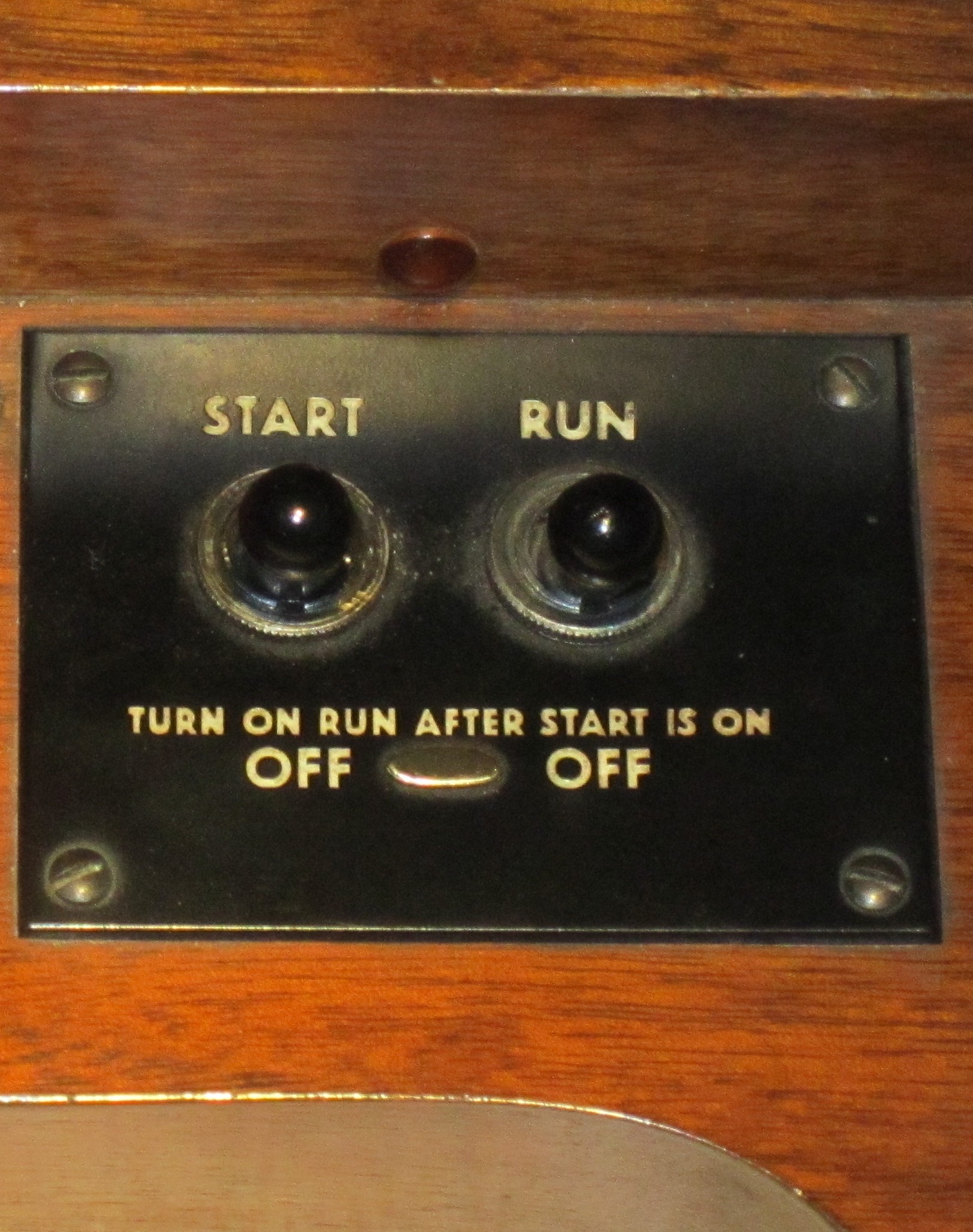
The start/run ritual. From cold, the operator holds the Start switch for 8–10 seconds while the shaded-pole start motor spins the generator up; then, with the generator near synchronous speed, the operator flicks Run. Throwing Run simultaneously energizes the synchronous motor and inserts a series resistor in the start-motor circuit, so the synchronous motor captures and the start motor falls away (bentonelectronics.com, Console Start and Run Switch Wiring; Hammond-Leslie FAQ, theatreorgans.com).
Warn: Flicking Run before the start motor has the generator near speed leaves the synchronous motor unable to capture; it will hum and not turn. Hold Start the full interval. Motor lubrication is a maintenance item, not a theory-of-operation item — see Vol 07 §“Oiling.”
2.3 The tonewheel generator
2.3.1 Wheel and pickup geometry
Each tone is generated by a steel tonewheel: a disc whose rim is cut with a number of smooth, sine-shaped high/low teeth. The wheel rotates immediately adjacent to a rod magnet carrying a coil pickup — an arrangement closely analogous to an electric-guitar pickup (dairiki.org, Tone Generator; electricdruid.net). As each tooth approaches and recedes across the small air gap, it modulates the reluctance of the magnetic circuit, and the changing flux induces an EMF in the coil. Because the teeth are sine-profiled rather than square, the induced voltage is a near-sinusoid at the tooth-passing frequency — the physical origin of the B-3’s characteristically pure per-wheel tone (dairiki.org; electricdruid.net).
Physical dimensions. Tonewheels are approximately 2 inches (51 mm) in diameter and machined from soft iron (dairiki.org ToneWheel). Each pickup is built around a magnetized rod approximately ½ inch (12.7 mm) in diameter and 4 inches (102 mm) long, with the coil wound near one end; the magnet tip is ground to a sharp edge and positioned close to the tonewheel rim (bentonelectronics.com, Generator Pick-Ups; bentonelectronics.com, Servicing the Hammond Tone Generator).
Coil sizing and harmonic damping. Pickup coils are not uniform across the generator: higher-frequency pickups use smaller coils; lower-frequency pickups use larger coils with correspondingly larger pole pieces to develop usable output at slower tooth-passing rates (bentonelectronics.com, Servicing the Hammond Tone Generator). Some lower-frequency coils carry copper rings around the magnet rod; eddy-current loss in these rings rises steeply with frequency, selectively suppressing harmonic distortion products from the coil and thereby improving sinusoidal purity — the effect is small for the fundamental but significant for its harmonics (bentonelectronics.com, Generator Pick-Ups).
Output level and shunt filtering. Calibrated coil output across the 91 active tonewheels typically ranges from approximately 9 mV to 21 mV peak-to-peak (stefanv.com, Hammond Tonewheel Generator Capacitor Replacement and Calibration). A shunt capacitor at each coil output forms a simple low-pass filter to suppress residual harmonic content: the service specification calls for 0.255 µF for tones 49–54 and 0.105 µF for tones 55–91; modern service practice substitutes 0.27 µF and 0.10 µF respectively, rated at 200 V (bentonelectronics.com, Servicing the Hammond Tone Generator; stefanv.com).
Air gap. The gap between the magnet tip and the wheel rim is set at the factory with the magnet adjustment screw while monitoring output on a meter. Hammond does not recommend field adjustment of this gap without factory calibration equipment; an incorrect gap changes both output amplitude and waveform purity (bentonelectronics.com, Generator Pick-Ups).
2.3.2 Frequency derivation
Pitch is purely geometric. For a wheel with T teeth turning at N RPM, the tooth-passing (and therefore output) frequency is:
f (Hz) = (N / 60) × T × (driving-gear teeth / driven-gear teeth)
       = 20 rev/s × T × R          (on 60 Hz mains, where N = 1200 RPM)
where R is the gear ratio coupling that wheel to the 1200 RPM main shaft (dairiki.org GearRatio; electricdruid.net). Worked example for the A above middle C: with a 16-tooth wheel and the gear pair 88/64,
f = (1200 / 60) × 16 × (88 / 64) = 20 × 16 × 1.375 = 440.0 Hz— i.e. A = 440 Hz exactly (dairiki.org GearRatio; electricdruid.net).
2.3.3 Wheels, gears, and grouping
The generator holds 96 tonewheels in total, of which 91 are active sound sources and the remaining 5 are blank balance wheels (dairiki.org Tone Generator; hammondwiki.org; matches Vol 01). The 96 figure is itself geometric: 24 driving gears × 2 driven gears × 2 tonewheels = 96 (dairiki.org). Wheels are distributed into shielded bins along the shaft; within a bin the two wheels on the same side of the drive shaft are tuned four octaves apart, an arrangement that keeps magnetically adjacent wheels far apart in frequency to suppress crosstalk (dairiki.org Tone Generator). Tooth counts double each octave — 2, 4, 8, 16, 32, 64, 128 — with the top octave capped at 192 teeth rather than 256, which is why the highest wheels carry a slightly larger tuning error (see below) (dairiki.org ToneWheel; goodeveca.net, Hammond Tone Wheel Spec).
2.3.4 Tuning: integer gears approximating equal temperament
Equal temperament wants each semitone to be the twelfth root of two (≈ 1.059463) times the one below it — an irrational ratio that no pair of integer-toothed gears can hit exactly. Hammond therefore chose, for the twelve semitones, the integer gear pairs whose ratios land closest to the ideal, tuned so that A = 440 Hz is exact (dairiki.org GearRatio; goodeveca.net). The classic twelve-ratio set:
Table 1 — (dairiki.org GearRatio; goodeveca.net). The classic twelve-ratio set
| Note | Driving | Driven | Characteristic ratio |
|---|---|---|---|
| C | 85 | 104 | 0.817308 |
| C# | 71 | 82 | 0.865854 |
| D | 67 | 73 | 0.917808 |
| D# | 70 | 72 | 0.972222 |
| E | 69 | 67 | 1.029851 |
| F | 54 | 99 | 0.545455 |
| F# | 37 | 64 | 0.578125 |
| G | 49 | 80 | 0.612500 |
| G# | 48 | 74 | 0.648649 |
| A | 66 | 96 | 0.687500 |
| A# | 67 | 92 | 0.728261 |
| B | 54 | 70 | 0.771429 |
Source: dairiki.org GearRatio (the table normalizes each semitone to a characteristic ratio; the actual gear-tooth pair used in a given octave is scaled to realize that same ratio — e.g. the A wheel above uses 88/64, which is the A ratio taken up an octave).
The residual error is tiny but deliberate-feeling: in the first seven octaves the worst offender, G#, is ~0.69 cents flat, and in the highest octave the 192-tooth cap puts C# about 1.93 cents sharp (dairiki.org GearRatio). The output frequencies are thus neither exactly equal-tempered (only A is exact) nor exact integer harmonics of one another — they sit close to both (goodeveca.net). That controlled mistuning is one source of the gentle beating the instrument is loved for (the “Hammond beats”).
A representative frequency subset (the full 91-wheel table is large; see goodeveca.net Hammond Tone Wheel Spec and dairiki.org for all 91):
Table 2 — Hammond Tone Wheel Spec and dairiki.org for all 91)
| Note (octave) | Wheel teeth × octave factor | Frequency (Hz) |
|---|---|---|
| C (low) | 2-tooth class | 32.692 |
| A (low) | 2-tooth, 88/64 | 55.000 |
| A (ref) | 16-tooth, 88/64 | 440.000 |
| A (high) | 128-tooth class | 3520.000 |
| C (high) | 128-tooth class | 2092.308 |
Source: goodeveca.net Hammond Tone Wheel Spec (representative values; A is exact, C-class wheels carry the ~equal-temperament approximation error).
Note: Because A is the only exactly-standard pitch, the whole keyboard is tuned “from A outward.” This is also the historical reason Hammond’s A-wheel frequency is sometimes credited with reinforcing 440 Hz as the concert-pitch standard (goodeveca.net).
2.4 Additive synthesis & the drawbars
The B-3 builds timbre by adding discrete harmonics, not by filtering a rich waveform. Each of the nine drawbars per manual taps the matching transformer at a chosen level for one harmonic footage; the player slides each bar through nine positions (0 = off … 8 = full) to set that harmonic’s contribution, and the bus sums them (electricdruid.net; Hammond B-3/C-3 Service Manual; hammondwiki.org). Pulling all nine to 8 yields the fullest, most organ-like stack; thinning the upper bars yields flute and string-like voices.
Drawbar level steps. Each increment of 1 corresponds to approximately 3 dB of additional output for that harmonic — incrementing by 2 roughly doubles the contribution, decrementing by 2 roughly halves it (dairiki.org Drawbars). This ≈ 3 dB/step relationship is a direct consequence of the matching transformer secondary tap design: each successive drawbar tap draws from a winding with approximately half the source impedance of the tap one position below it, yielding a roughly doubled signal voltage per step (dairiki.org Drawbars; Hammond B-3/C-3 Service Manual).
The footages, harmonic numbers, drawbar colors, and interval names (relative to the played note as the 8′ fundamental):
Table 3 — played note as the 8′ fundamental)
| Drawbar | Footage | Color | Harmonic no. | Harmonic role | Interval above 8′ fundamental |
|---|---|---|---|---|---|
| 1 | 16′ | brown | sub-fund. | Sub-fundamental | one octave below |
| 2 | 5⅓′ | brown | sub-3rd | Sub-third (quint) | a 5th above |
| 3 | 8′ | white | 1st | Fundamental | unison — the played pitch |
| 4 | 4′ | white | 2nd | 2nd harmonic | one octave above |
| 5 | 2⅔′ | black | 3rd | 3rd harmonic | octave + 5th (the 12th) |
| 6 | 2′ | white | 4th | 4th harmonic | two octaves above |
| 7 | 1⅗′ | black | 5th | 5th harmonic | two octaves + major 3rd (17th) |
| 8 | 1⅓′ | black | 6th | 6th harmonic | two octaves + 5th (19th) |
| 9 | 1′ | white | 8th | 8th harmonic | three octaves above (22nd) |
Sources: dairiki.org Drawbars; electricdruid.net; Hammond B-3/C-3 Service Manual; hammondwiki.org. The two brown drawbars (16′, 5⅓′) are the sub-harmonics below the fundamental; the white bars address octave-related harmonics; the three black bars (2⅔′, 1⅗′, 1⅓′ — the non-octave “mutation” footages) add the fifths and thirds that give the stack its reedy, pipe-like quality.
Tip: The B-3 has no 7th-harmonic drawbar — the harmonic series skips from the 6th (1⅓′) to the 8th (1′). That gap is part of why the additive stack reads as “organ” rather than “sawtooth.”
2.5 The key-contact matrix & busbars
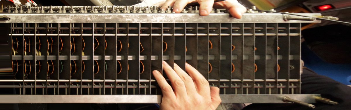
Each manual key does not switch one signal — it switches nine. Pressing a key closes nine contacts, one per footage, each wiping a busbar that already carries that footage’s frequency for that key (drawn from the appropriate tonewheel through the matching transformer). The nine closed contacts deliver nine frequencies to the nine drawbar mixers; the drawbars then set how much of each reaches the bus (electricdruid.net; Hammond B-3/C-3 Service Manual).
Across both manuals with 61 keys per manual and 9 contacts per key, the keyboard alone accounts for over 1,100 individual switch contacts; including the 25-note pedalboard and remaining console contacts the total is cited as approximately 1,220 switch contacts across the full console (electricdruid.net). Every one of them carries a live audio-level AC signal — not a logic or control-level signal — which makes contact cleanliness a direct audio quality concern rather than a reliability-only concern.
Key-click origin. The nine contacts do not make or break in perfect unison, and the contacts bounce as they close and open. Switching nine live AC signals straight to the mixers through imperfect, non-simultaneous contacts produces a brief broadband transient at note-on and note-off — the famous key-click (electricdruid.net). It is a switching artifact, not a designed waveform, but it is intrinsic to how the matrix works and is a defining part of the attack; restoration that “cleans” the contacts too aggressively can dull it (see Vol 09 §“Key contacts / the Hammond fix”).
Note: Because every key carries all nine footages on its own contact set, contact condition is per-note and per-footage. A single oxidized contact mutes one harmonic of one note — diagnosable precisely because the matrix has no signal redundancy.
2.6 Foldback
There are only 91 distinct frequencies, yet each 61-note manual, read across nine footages, demands pitches both above and below what 91 wheels span. Foldback resolves this by reusing wheels at the extremes rather than adding more (hammondwiki.org; electricdruid.net):
- At the top. The upper drawbars (especially 1′, 1⅗′, 1⅓′, 2⅔′) on the top keys would call for pitches above the highest active tonewheel. Instead the top octave of each affected footage folds back down an octave, reusing the highest real wheels so the upper drawbars on the top keys repeat the octave below rather than running off the top of the generator (electricdruid.net; hammondwiki.org). The foldback boundaries by footage, expressed as generator tonewheel numbers, are:
Table 4 — by footage, expressed as generator tonewheel numbers, are
| Footage (drawbar) | Folds back from tonewheel | Note at that boundary |
|---|---|---|
| 2⅔′ (3rd harmonic) | 80 | highest C in generator |
| 2′ (4th harmonic) | 56 | G of the top octave |
| 1⅗′ (5th harmonic) | 52 | D# of the top octave |
| 1′ (8th harmonic) | 44 | G, fourth octave from top |
Source: electricdruid.net. Above each boundary the footage wraps to the highest available wheel of that series rather than demanding a non-existent higher wheel.
- At the bottom. The 16′ sub-fundamental and the low-footage contacts on the bottom keys would call for sub-audio pitches requiring extra low wheels that do not exist. The low end therefore folds up: the bottom octave of the low-footage assignments reuses tones in the range of generator tonewheels 13–24 rather than demanding wheels below the generator’s lowest, keeping the bass from disappearing into infrasound (electricdruid.net; hammondwiki.org).
Without foldback the design would need on the order of 61 + 36 + 12 = 109 distinct tones to cover every footage at every key; foldback is precisely what lets 91 wheels do the job (electricdruid.net). The audible consequence is that at the extreme top of the manual, pulling more upper drawbars stops adding higher pitch and instead reinforces the octave — a hallmark of the real instrument and one of the foldback tells noted in Vol 01.
Tip: Foldback is why a glissando to the very top of the manual “flattens out” in brightness instead of getting endlessly shriller — the upper harmonics have wrapped onto wheels that already exist.
2.7 From generator to output (matching transformer → AO-28)
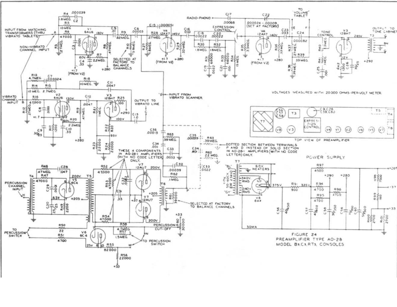
Each tonewheel’s coil feeds a matching transformer, and it is this transformer the nine drawbars tap at their nine positions — the drawbar is, in effect, a multi-tap attenuator on the transformer secondary, which is why drawbar level changes are smooth and load the wheel consistently (electricdruid.net; Hammond B-3/C-3 Service Manual). The summed drawbar bus is buffered and voiced by the AO-28 tube preamplifier, the preamp fitted to the B-3/C-3 from the 1950s through the end of production in 1975. Its drive level is adjustable — raising it brings on the overdriven “growl” players prize (bentonelectronics.com, Servicing the Hammond B-3 Type Pre-Amp; hammondtoday.com, AO-28 schematic).
The diagram below traces this final stage in detail — from the coil’s millivolt output through the shunt capacitor filter and the matching transformer’s multi-tap secondary, through the drawbar attenuators and summing bus, to the AO-28 input and the 6-pin Amphenol output:
The AO-28 output leaves the console through the 6-pin Amphenol connector as a balanced line-level signal to the Leslie 122, whose own 40 W tube amplifier does the power amplification (the B-3 contains no power amp and no speaker — Vol 01 §“What the B-3 is”). This is line level, not microphone or instrument level: it is a balanced feed intended to drive the Leslie’s input stage, not a high-impedance instrument output.
Warn: The exact AO-28 output voltage / dBu reference and source/load impedance into the Leslie 122 were not confirmable from the sources consulted for this volume. They are therefore not stated here as hard figures — no value is invented. The Leslie 122 interface (6-pin pinout, balanced line, 40 W amp, 800 Hz crossover) and its measured levels are developed in Vol 04 §4.1; the studio-side levels in dBu are treated in Vol 17. Treat any specific dBu/Ω figure as (est.) until confirmed there. AO-28 component-level service — tube types, bias points, recapping, and the percussion circuit — is the subject of Vol 08 §“Power, Recapping, the AO-28 Preamp & Percussion Circuit”.
Sources
- Hammond B-3 / C-3 Service Manual (Hammond Organ Company) — generator, drawbars, key contacts, matching transformer, preamp, connector.
- dairiki.org / HammondWiki — Tone Generator (96 wheels, 91 active, 5 blank; 24×2×2 = 96; bin grouping, four-octave spacing) and GearRatio (1200 RPM / 20 rev/s, frequency formula, the twelve gear ratios, A = 440 exact, ~0.69 cent and ~1.93 cent tuning errors); ToneWheel (~2 inch / 51 mm diameter, soft iron, 192-tooth top-octave cap); Drawbars (9 positions, ≈ 3 dB/step, secondary tap impedance halving per step, drawbar colors brown/white/black).
- electricdruid.net, Technical aspects of the Hammond Organ — frequency formula and worked A = 440 example, drawbar footages → harmonics, nine key contacts and key-click origin, ~1220 total console switch contacts, foldback boundaries by tonewheel number (3rd harmonic: tone 80; 4th: tone 56; 5th: tone 52; 8th: tone 44), bottom foldback tones 13–24, 61+36+12 = 109 vs 91.
- goodeveca.net, Hammond Tone Wheel Spec — representative frequency table, 91 active wheels (92–96 blank), 192-tooth top-octave cap, A-as-only-exact-pitch note.
- bentonelectronics.com — Hammond Synchronous Run Motor (non-self-starting, 1200/1500 RPM, ~180 Ω per coil / ~90 Ω both in parallel, 120 pulses/s); Hammond Generator Start Motor (shaded-pole induction, two springs: clutch + return); Console Start and Run Switch Wiring; Generator Pick-Ups (rod magnet ~½ in × 4 in / 12.7 mm × 102 mm, coil sizes by frequency range, copper rings on low-frequency coils, factory-set air gap); Servicing the Hammond Tone Generator (shunt caps 0.255 µF / 0.105 µF); Servicing the Hammond B-3 Type Pre-Amp (AO-28, drive level / growl).
- stefanv.com, Hammond Tonewheel Generator Capacitor Replacement and Calibration — coil output 12–21 mV peak-to-peak, cap replacement values 0.27 µF / 0.10 µF at 200 V.
- hammondtoday.com — AO-28 schematic and parts list. hammondwiki.org — foldback, wheel count. theatreorgans.com — Hammond-Leslie FAQ (start/run procedure).
Cross-references: drawbars, presets, percussion, vibrato/chorus scanner, and the start/run controls as an operator surface in Vol 03; the Leslie 122 interface, 6-pin pinout, 40 W amp, and measured line levels in Vol 04 §4.1; studio-side levels (dBu) and interfacing in Vol 17; the 25-note pedal generation and Trek II bass path in Vol 05; AO-28 tube complement, bias points, recapping, and percussion circuit in Vol 08.
Comments (0)