Hammond B-3 · Volume 7
Hammond B-3 — Vol 07: Recording & Integration
This volume covers capturing the B-3 → Leslie 122 rig in a studio and wiring it into the rest of the room. The governing fact is that the instrument’s voice is acoustic and in motion: the rotating treble horn and bass drum (Vol 04 §“Horn & drum rotors”) produce Doppler frequency modulation, amplitude modulation, and sliding comb filtering in the air of the room, not on a wire. Recording the rig therefore means mic’ing the Leslie, almost always — the classic three-mic arrangement (a pair on the top horn for the stereo swirl plus one on the bottom drum), with explicit attention to mic choice, distance, rotor wind noise, and inter-mic phase. The volume then handles the supporting questions: the level and impedance interfaces (mic level vs instrument level vs line level, and the very hot signal — a nominal ~3–4 V RMS, with peaks running substantially higher at full drawbars and open swell — that the AO-28 can present to the 122), the half-moon speed switch and combo-preamp/line-tap adapters, why DI’ing the organ misses the point, the scope and limits of aftermarket MIDI retrofits, and how the mics land on the studio’s preamps, gain-staging, and isolation. Rotary theory and the cabinet’s electrical anatomy are Vol 04; the console and AO-28 are Vol 02; the half-moon switch as a control is Vol 03 §3.x and Vol 04 §“Fast/slow”; cabinet service is Vol 06.
Note: Throughout this volume, level references are stated explicitly because they are the whole game at the interface: mic level ≈ −60 to −40 dBu, instrument (Hi-Z) level roughly −20 to −10 dBu into a high-impedance input, consumer line level = −10 dBV (≈ 0.316 V RMS), and pro line level = +4 dBu (≈ 1.23 V RMS). dBu references 0.775 V RMS; dBV references 1.0 V RMS. A signal called simply “line level” without a reference is ambiguous and is avoided here.
Why mic the Leslie (not DI the organ)
The Leslie effect is a spatial phenomenon. As Vol 04 §“Why a rotating speaker” sets out, the swirl is the superposition of three things that only exist once sound is radiating from a moving source into a room: pitch modulation from the Doppler shift of the swinging horn mouth, level modulation from the horn’s directional lobe sweeping past the listening point, and comb filtering as the path-length difference between direct and reflected sound slides continuously. None of that exists on the wire upstream of the cabinet. A direct tap of the organ’s output — at the AO-28 (Vol 02 §2.x) or via a line-out adapter — carries the drawbar tone, the key click, the percussion, and the scanner vibrato/chorus (Vol 03 §3.4), but it is a stationary signal with no rotation in it at all.
The practical consequence: to record “a Hammond through a Leslie,” engineers put microphones in front of the spinning cabinet. The motion has to be transduced acoustically because that is the only place it exists. A line/DI tap is reserved for the cases in §“Interfacing the rig” — re-amping into a different cabinet later, feeding a console submix, or capturing a dry reference alongside the mic’d sound — and even then it is an adjunct, not a substitute. This is the load-bearing rationale developed further in §“DI vs Leslie”.
Tip: A useful studio move is to record the mic’d Leslie and a dry line tap on separate tracks simultaneously (where a line-out adapter exists). The mics are the keeper; the dry track is insurance — it can be re-amped through the Leslie again, sent to a rotary emulation, or blended under the live cabinet for extra body. It is never a replacement for the mics.
Mic’ing the Leslie 122
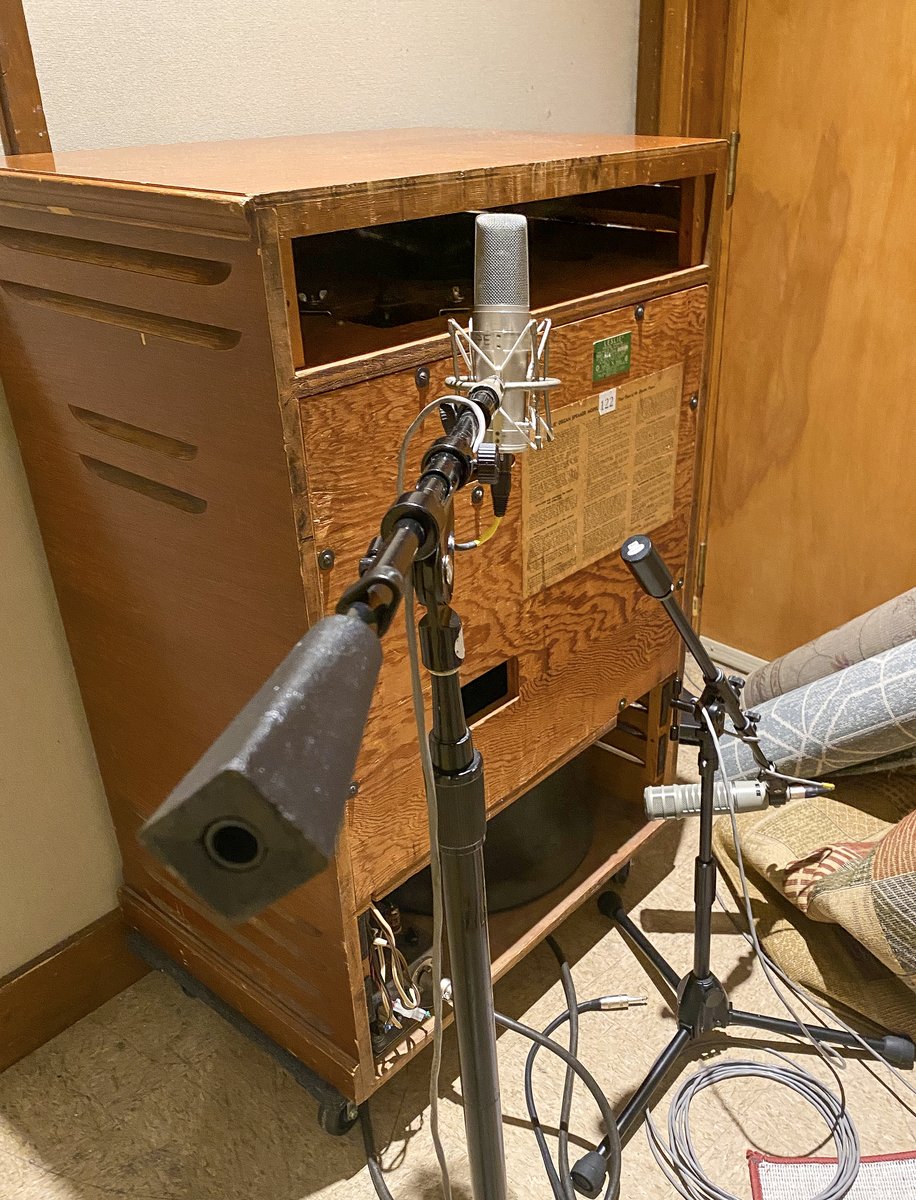
The canonical studio technique for the 122 is three microphones: a stereo pair on the upper treble-horn compartment and one microphone on the lower bass-rotor vents (Sound on Sound, “How do you record a Leslie speaker?”; Shure, “Miking the Legendary Leslie Tone Cabinet”; recordingmag.com, “Miking the Hammond and Leslie”). The pair on top captures the fast, directional swirl in stereo; the single mic on the bottom captures the slower bass wash, which is largely mono in character and does not need a pair. The back (and sometimes a side louvre panel) of the cabinet is removed so the mics see the rotating elements directly.
The top pair is the critical decision. Its geometry sets both the stereo width and the apparent depth of the rotary effect. Two common placements are documented (Sound on Sound; HammondWiki, “Leslie Recording Techniques”):
- Mics on opposite sides of the cabinet, facing in toward the horn — the most extreme stereo, the widest swirl. But because the 122 has only one acoustically live horn (the other is a sealed dummy counterweight, Vol 04 §“Horn & drum rotors”), two mics 180° apart each hear the live horn’s pass at a different instant, which can make the rotor sound like it is turning twice as fast as it really is, and which complicates phase (see below).
- Mics angled in toward the horn’s pivot from the two sides of the open rear panel — a more natural, familiar stereo image with a truer sense of speed; the usual starting point in a controlled studio.
For the bottom, a single dynamic placed within a ~6–12 inch (15–30 cm) working range from the lower louvres is a common starting point (Shure cites ~12 in for a single bottom mic; Sound on Sound cautions against placing it too close). Placing the bottom mic on the cabinet side away from the amplifier’s speed-changeover relay reduces audible relay-click pickup on speed changes (Sound on Sound, on relay-click placement).
Distance is a trade-off. Close mic’ing emphasises the Doppler/AM depth and rejects the room, but the rotating horn throws a real blast of air — wind/turbulence noise is a genuine problem if a mic is placed too close, and foam windscreens help (Sound on Sound; Shure). Backing the mics off picks up more room and a gentler, more “in the air” rotary sound at the cost of depth and isolation. In a large or square room, closer mic’ing also tames low-frequency reflections that otherwise muddy the bass rotor (Sound on Sound).
A mono capture is entirely valid: a single mic on the top horn (optionally summed with one on the bottom) gives a usable rotary sound when stereo is not wanted or not available, and it sidesteps the inter-mic phase questions below.
Note (phase / polarity): With the classic 2-up/1-down array there are three capsules hearing overlapping energy, so polarity and phase need checking, not assuming. The two top mics, especially when spread wide, hear the single live horn at different times — this is a time-of-arrival difference, not a simple polarity flip, so the usual “flip the polarity if it sounds thin” rule may not cleanly fix a hollow image (Sound on Sound; HammondWiki). The bottom mic, capturing mostly sub-800 Hz energy, can also fight the top pair in the crossover overlap region around 800 Hz (the band radiated by both rotors, Vol 04 §“The 800 Hz crossover”). Practical procedure: check each mic’s polarity against the others in mono, then audition the stereo image, adjusting mic positions (not just polarity switches) until the swirl is coherent and the low end stays solid in mono.
Tip: Dynamic mics dominate the tradition because they shrug off the high SPL and air blast and add a flattering midrange bump. Condensers on top give more top-end detail and air but are more prone to wind noise and overload; if used, keep them a touch farther back and windscreened.
Mic position → mic type → what it captures
| Position | Suggested mic type | Captures |
|---|---|---|
| Top horn, mic A (one side of open rear) | Dynamic (e.g. Shure SM57) or small-diaphragm condenser | One side of the treble swirl; left of the stereo image; strong Doppler/AM detail above 800 Hz |
| Top horn, mic B (other side) | Matched to mic A (e.g. second SM57; or condenser) | Other side of the treble swirl; right of the stereo image; together the pair sets stereo width + apparent speed |
| Bottom drum/rotor (≈ 9 in / 23 cm from lower louvres, away from relay side) | Dynamic (e.g. Sennheiser MD421 or EV RE20; an SM57 also works) | The sub-800 Hz bass wash; body and low-frequency “throb”; largely mono |
| Mono alternative — single top mic | Dynamic (SM57) or condenser | Whole rotary effect in mono; no inter-mic phase concerns |
Mic choices from Sound on Sound, Shure, and recordingmag.com (SM57 pair on the horn, MD421/RE20 on the drum are the most-cited combination). Exact models are illustrative of the class, not prescriptive.
SVG — three-mic placement on the Leslie 122
Levels & impedance
Two distinct interfaces matter when recording the rig, and they live at opposite ends of the level scale:
-
The Leslie mic outputs → studio mic preamps. Each microphone on the cabinet produces mic level (≈ −60 to −40 dBu) on a low-impedance balanced output, and must land on a microphone input (a mic preamp with ~1–2 kΩ load and 40–60 dB of available gain). This is ordinary mic’ing; the only Leslie-specific wrinkles are high SPL (the cabinet is loud — see §“Where it sits”) and rotor wind noise.
-
The organ/Leslie line feed → a line or instrument input (only if tapped at all). The 122’s input is fed by the AO-28 at a very hot ~3–4 V RMS, balanced (Vol 04 §“The 6-pin balanced connection”; organforum.com). For orientation, 3–4 V RMS is roughly +12 to +14 dBu — hotter than +4 dBu pro line level, an order of magnitude above mic level, and not something to ever route into a mic input. If a recordist taps the organ’s signal (via a line-out adapter, §“Interfacing the rig”), it must go to a line input (consumer −10 dBV or pro +4 dBu, with the adapter’s level trimmed to match) or an instrument/DI input, never a mic input. The classic interface error is feeding a hot organ/Leslie line into a mic preamp and clipping it instantly.
Warn: The 6-pin Leslie cable is not a signal patch cord. Per Vol 04 §“The 6-pin balanced connection” it carries AC mains and a high-voltage DC feed (~300 VDC) alongside the balanced audio. It must never be patched into recording gear, mated/de-mated live, or probed for a “line out.” Any line tap is taken from a purpose-built adapter (next section), not from this connector.
Signal → nominal level → correct interface input
| Signal | Nominal level (with reference) | Correct interface input |
|---|---|---|
| Leslie top/bottom microphones | Mic level, ≈ −60 to −40 dBu (0 dBu = 0.775 V RMS) | Mic preamp input (XLR, ~1–2 kΩ, 40–60 dB gain) |
| AO-28 → 122 internal feed (do NOT tap directly) | ≈ 3–4 V RMS balanced ≈ +12 to +14 dBu (est. dBu conversion) | None for recording — it drives the 122; never a mic input |
| Trek II OBL-2 / line-out adapter from the console | Line level, set by the adapter’s level control to −10 dBV (≈ 0.316 V) or +4 dBu (≈ 1.23 V) | Line input (interface/console line in), level-matched |
| Combo-preamp instrument output / re-amp send | Instrument (Hi-Z) level, ≈ −20 to −10 dBu into a high-Z load | Instrument / DI input (≈ 0.5–1 MΩ) |
| Reissue Leslie 122H/142H line input (reference point) | ~100 mV (−18 dBu), 10 kΩ (hammondsuzuki.com, via Vol 04) | (Cabinet input, not a recorder input — listed for level orientation) |
The +12 to +14 dBu figure for the AO-28 feed is an (est.) dBu conversion of the cited 3–4 V RMS, not an independently published spec; it is given only to place that feed correctly on the level scale (well above pro line level). No level here is invented — they are conversions of, or citations to, the figures in Vol 04 and the cited sources.
Interfacing the rig: half-moon, combo preamps, line taps
The half-moon switch. Speed selection is done at the organ by the half-moon switch (the semicircular tremolo/chorale, and often off/brake, lever within reach of the manuals — Vol 03 §3.x, Vol 04 §“Fast/slow”). It carries no audio; it controls the changeover relay inside the 122, with the switching information riding the same 6-pin balanced cable as a common-mode DC (Vol 04 §“The 6-pin balanced connection”). For recording, this means the player drives the speed changes musically during the take — the ramp-up/ramp-down inertia sweeps (Vol 04) are part of the performance the mics capture, not something added later. There is no separate “speed control out” to record.
Combo preamps / adapters. A family of small interface boxes adapts the Leslie/Hammond connection for cases the original 6-pin scheme does not cover (captain-foldback.com, “Leslie Combo Preamp”; tonewheelgeneral.com, Trek II):
- A universal combo preamp such as the Trek II UC-1A lets any 1/4” line/instrument source — a clonewheel, synth, guitar, or a console submix — drive a real Leslie (122, 147, 760, etc.), providing the correct interface, footswitch tremolo/chorale control, power switching, and level/tone trim (tonewheelgeneral.com; reverb.com UC-1A listings). This is how a 122 gets driven from a non-Hammond source in the studio.
- A line-out adapter such as the Trek II OBL-2 taps a standard Hammond console (B-3/C-3/A-100) to a 1/4” output jack with a level control to match the destination’s input (pianofarm.com OBL-2 listing). It gives a recordist a dry console feed without disturbing the Leslie drive. The level must be trimmed to the target line input (−10 dBV or +4 dBu) per §“Levels & impedance”.
Tip: A combo preamp is also the safe way to audition a console against several Leslies, or to drive a 122 from a 147-style source (or vice-versa), without rewiring the 6-pin “6H”/“6W” cabling that Vol 04 §“The 6-pin balanced connection” warns is not interchangeable. Speed control and level live on the adapter, not on a re-pinned cable.
Line taps are adjuncts. Where an OBL-2 or equivalent provides a dry line output, it is recorded in addition to the Leslie mics (§“Why mic the Leslie”), for re-amping or blending — not as the primary organ sound.
DI vs Leslie
The temptation to “just DI the organ” and skip the loud, heavy, mechanically noisy cabinet is understandable and almost always wrong for the B-3 voice. A DI/line tap captures the console’s stationary output — drawbars, key click, percussion, scanner vibrato/chorus (Vol 03 §3.4) — but no rotation, because the rotation does not exist until the sound is radiating from the moving horn and drum into the room (§“Why mic the Leslie”; Vol 04 §“Why a rotating speaker”). The result sounds like a flat, un-Leslied organ: recognisably a Hammond, but missing the swirl that defines the instrument in nearly every record that features it.
Legitimate uses of a DI/line tap, all secondary:
- A dry insurance/re-amp track alongside the mic’d Leslie (§“Why mic the Leslie”, Tip), to re-amp through the cabinet again or to feed a rotary emulation later.
- Feeding a rotary-speaker simulation when a real Leslie is unavailable or impractical (a software/hardware emulation generates the Doppler/AM/comb effects from the dry signal). This is a substitute for the cabinet, used knowingly, not a way to capture the real one.
- Console submix / monitoring where a clean organ feed is needed for headphones or a sub-bus and the Leslie is mic’d separately.
Note: “DI the organ directly” also runs into the level problem of §“Levels & impedance”: there is no convenient low-level direct output on a vintage console, and the internal AO-28 feed is the hot ~3–4 V RMS balanced drive intended for the cabinet, not a DI source. A clean dry feed comes from a line-out adapter (OBL-2 or equivalent) at a controlled line level — not from probing the organ’s amp or the 6-pin cable.
MIDI retrofits
A tonewheel B-3 is fundamentally not a MIDI instrument. Its keyboards are banks of mechanical key contacts that tap a running tonewheel generator (Vol 02 §2.x); there is no digital scan, no note data, and no velocity sensing anywhere in the original design. MIDI is therefore always an aftermarket retrofit, and a fairly invasive one. The honest scope:
- What retrofit kits do. Third-party encoders (e.g. MIDI Boutique’s contact encoders; Analog Outfitters’ ORGANiC board) read the form-A key contacts — the same single-make switch type the Hammond uses — and emit MIDI note on/off so the manuals can drive external sound modules or a DAW (organforum.com, “MIDI encoders for tonewheel Hammond retrofit”; reverb.com, Analog Outfitters ORGANiC; dairiki.org HammondWiki “Hammond Modifications”).
- The compromises. Most retrofits have no velocity sensitivity (the contacts are simple on/off), installation means getting inside the keyboard chassis and wiring each contact (some kits require sacrificing a drawbar set’s contacts for the pickoff), and the better-integrated systems (e.g. ORGANiC) go to lengths to preserve the original key-contact and bus-bar wiring rather than gut it. It is described in the field as an expensive, serious modification (organforum.com; harmonycentral.com retrofit threads).
- What it does not do. A MIDI retrofit makes the B-3’s keyboards a controller; it does not turn the tonewheel generator, drawbars, percussion, or scanner into MIDI-addressable parameters, and it does not capture or sequence the Leslie. The organ’s own voice still reaches the recorder the only way it can — through the Leslie, mic’d (§“Mic’ing the Leslie 122”).
Note: Scope discipline matters here: this volume documents that retrofit kits exist and what class of thing they are (key-contact MIDI encoders, no velocity, invasive install), not a specific installation procedure. Anyone considering a retrofit should treat it as a chassis-opening modification with the safety implications of Vol 06, and confirm current product specifics against the vendor — the field offerings change and are not standardised.
Where it sits in the studio
The mic’d Leslie integrates into the rest of the room as a loud, mechanically noisy acoustic source feeding a normal mic-preamp-to-DAW chain. The chain and its gain-staging:
- Leslie microphones (2–3) → mic preamps. The top pair and bottom mic run on balanced mic cables to the studio’s Audio Control / interface area (the room’s mic preamps and converters — referenced generically as another part of the MusicStudio hub). Each preamp is set for mic level input (§“Levels & impedance”) with 40–60 dB of gain as needed.
- Gain-staging. Set each preamp so the loudest passages peak with healthy headroom (a common target is roughly −18 to −12 dBFS average on the converter, peaks well short of 0 dBFS) — the B-3 through a hard-driven Leslie has wide dynamics and transient key-click content, so leave room. Match the two top-mic preamps’ gains to each other so the stereo image stays centred and the swirl is symmetrical; the bottom mic is set independently for low-end weight.
- Converters → DAW. From the preamps the signals convert to digital and arrive in the DAW as two or three tracks (top L, top R, bottom), to be balanced, panned for stereo width, and routed onward to the Mixing & Monitoring area of the studio.
Isolation is a real concern. The 122 is a ~40 W tube-amp cabinet (Vol 04 §“The amplifier & power supply”) that is loud and, uniquely, mechanically noisy — spinning rotors, belts, and motors (Vol 04 §“Fast/slow”) add airborne mechanical sound and the changeover relay clicks on speed changes (§“Mic’ing the Leslie 122”). For a clean capture the cabinet wants acoustic isolation from other live sources (an iso booth or a separated corner), and the mics want positioning that favours the rotor sound over the motor/relay noise (bottom mic away from the relay side). The cabinet’s own console and amplifier carry the high-voltage hazards detailed in Vol 04 and Vol 06 — relevant in the studio because the cabinet is being opened (rear/side panels off) for mic access while energised; nothing inside the chassis is touched, and the 6-pin cable safety of §“Levels & impedance” stands.
Tip: Because the Leslie is captured acoustically, the room is part of the instrument. A tight, dead booth gives a controlled, close rotary sound that sits easily in a mix; a live room backed off the cabinet gives an open, three-dimensional swirl with the room’s reflections feeding the comb filtering (Vol 04 §“Why a rotating speaker”). Choose the space and mic distance together — they are one decision, made before the take, in the Audio Control / Mixing context of the wider studio.
Sources consulted: “Q: How do you record a Leslie speaker?” — soundonsound.com; “Miking the Legendary Leslie Tone Cabinet” — shure.com; “Miking the Hammond and Leslie” — recordingmag.com; “Leslie Recording Techniques” — dairiki.org (HammondWiki); “Miking a Leslie 122” — gearspace.com; Trek II UC-1A / OBL-2 combo-preamp and line-out product references — tonewheelgeneral.com, pianofarm.com, reverb.com, and captain-foldback.com (“Leslie Combo Preamp”); MIDI retrofit references — organforum.com (“MIDI encoders for tonewheel Hammond retrofit”), reverb.com (Analog Outfitters ORGANiC), harmonycentral.com, and dairiki.org (“Hammond Modifications”). Level references (dBu = 0.775 V RMS, dBV = 1.0 V RMS, −10 dBV / +4 dBu line standards, mic/instrument-level ranges) are standard audio-engineering references; the +12 to +14 dBu figure for the AO-28 feed is an estimated dBu conversion of the 3–4 V RMS value cited in Vol 04 (organforum.com) and is flagged “(est.)”. Cross-references: Vol 02 (theory/AO-28), Vol 03 §3.4 (scanner/half-moon as control), Vol 04 (Leslie 122 anatomy, rotary theory, 6-pin balanced connection, fast/slow), Vol 06 (high-voltage safety). No microphone distance, level, or impedance value has been invented; figures are cited or marked “(est.)”.