Wind Systems · Volume 1
Wind Systems — Vol 01: The Wind Chain
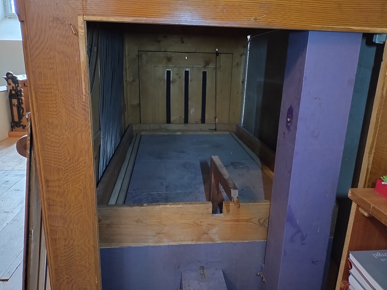
Every pipe organ, from a continuo box to a fairground band organ, is at heart a wind instrument played by machinery instead of lungs. Nothing sounds until air under a small, steady pressure is delivered to a pipe and let into its foot. This first volume defines the subject the whole series develops: what “wind” actually is in an organ, the chain of components that raises it and hands it to the pipes, and the two independent quantities — pressure and flow — that every later volume comes back to. The mechanism detail (how feeders pump, how a reservoir’s ribs keep pressure flat, how a tremulant shakes the column, how to size and build a small system) is deferred to Vols 2–7 and cross-referenced here. This volume is the map; the later ones are the territory.
The scale is deliberately general. The concrete busker-organ case — the John Smith Universal, its three 120°-phased feeders, its ~5 in H₂O sprung reservoir and spill valve — is fully worked in that instrument’s own dive (John Smith Universal, Vol 04) and is cited here as the small-scale example rather than repeated.
1.1 What “wind” means: a steady supply, not a puff
The word wind in organ-building is a term of art, and the first thing to unlearn is the everyday sense of a gust or a breath. Organ wind is a continuous, regulated supply of air held at a low, near-constant pressure for as long as the instrument is switched on or being cranked. It is not a puff delivered per note and it is not the moving airstream of a wind band’s clarinet. When a key is pressed, the action does not blow the pipe; it opens a valve (a pallet) that lets the pipe draw on a reservoir of air that was already sitting there at pressure, waiting. The supply is standing; the note taps it.
That distinction drives the entire architecture. Because the pipes must find their air already at the correct pressure the instant a valve opens — and must go on finding it, unchanged, whether one pipe or fifty are speaking — the wind system’s job is not primarily to move air but to hold a pressure against a demand that switches on and off unpredictably. Audsley frames the whole craft of the bellows-maker as the pursuit of a wind “absolutely steady” under all conditions of draw (Audsley, The Art of Organ Building), and Pykett, treating the same problem in modern terms, describes the reservoir as a low-pass reservoir of stored energy whose purpose is to decouple the intermittent supply from the intermittent demand (Pykett, pykett.org.uk, “The organ wind supply”). A puff would make a barrel organ; a held pressure makes an instrument that can be tuned.
1.2 The wind chain, end to end
Between the source of air and the mouth of a pipe lies a fixed sequence of components. The names vary by tradition and scale — a cathedral organ’s “blower and static reservoir” and a busker organ’s “crank and sprung bellows” are the same functional stages at different sizes — but the chain is invariant:
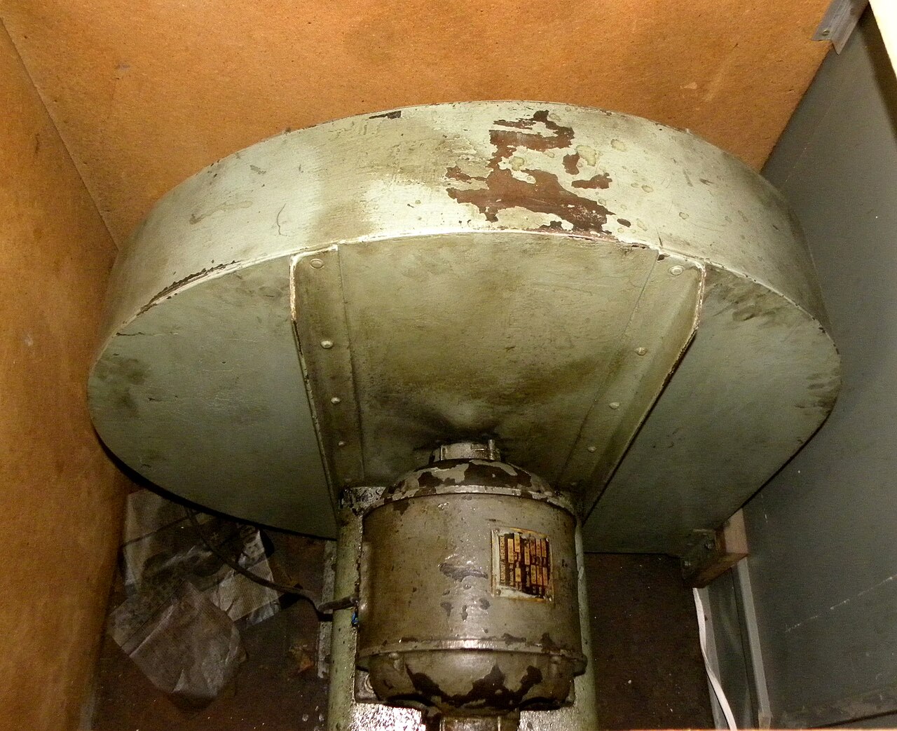
- The raiser (wind source). Whatever puts air into the system under pressure: hand- or foot-pumped feeders, a crank-driven feeder set, a falling weight, a water engine, or — since about 1900 — an electric centrifugal blower. The raiser delivers air that is, in general, neither smooth nor at a precisely held pressure. (Vol 02.)
- The reservoir / regulator. A store that both buffers the raiser’s pulsation and regulates the pressure to a set value, held by a spring or a weight and trimmed by a relief/spill valve. This is where an uneven supply becomes a flat, defined pressure. (Vol 03.)
- The wind trunk (conveyance). The duct — trunk, offset, or flexible hose — that carries regulated wind from the reservoir to the chest. Its cross-section must be generous: an undersized trunk throttles flow and lets pressure sag at the chest even while the reservoir reads correct. (Vol 04 §on sizing.)
- The chest / pallet box. The pressurized box beneath the pipes (called a pressure box or wind chest on a small organ, a soundboard on a large one). A pallet valve under each note, opened by the key or the paper roll, admits wind from the box into the pipe’s channel. (Detail: John Smith Universal, Vol 06.)
- The pipe. The load. A flue pipe converts the pressurized air into a jet at its windway, the jet drives an edge tone at the mouth, and the pipe’s resonator fixes the pitch. What the pipe demands of the chain — a specific pressure and a specific volume of air per second — is set here, and everything upstream exists to meet it. (How Organ Pipes Make Sound, Vol 2/6.)
The figure below shows the chain with pressure and flow annotated at each stage. The key visual point is that pressure is (ideally) constant along the whole chain from reservoir to pipe foot, while flow is zero until a pallet opens and then equals the running sum of what the sounding pipes draw.
1.3 Two independent quantities: pressure and flow
The single most important idea in the whole series is that a wind system is specified by two numbers that do not depend on one another: the pressure it holds and the flow it can supply. A system can hold a perfect pressure and still fail because it cannot supply enough air; it can have abundant air and be useless because it holds the wrong pressure. They are set by different parts of the chain and measured in different units.
1.3.1 Pressure — the water-gauge column
Pressure is the force per unit area the wind exerts, and by long convention it is quoted as the height of a water column it will support — inches of water (in H₂O) in the English tradition, millimetres of water (mm H₂O) metrically. The convention is not arbitrary: the reference instrument is a U-tube water manometer, a clear tube part-filled with water with one leg teed into the wind and one leg open to air. The wind pushes the water up the open leg, and the difference in the two levels, read off a ruler, is the pressure in inches (or mm) of water. The column is its own calibration; no gauge is needed (Audsley; Pykett). The manometer, static-vs-dynamic pressure, and measurement technique are Vol 04’s subject.
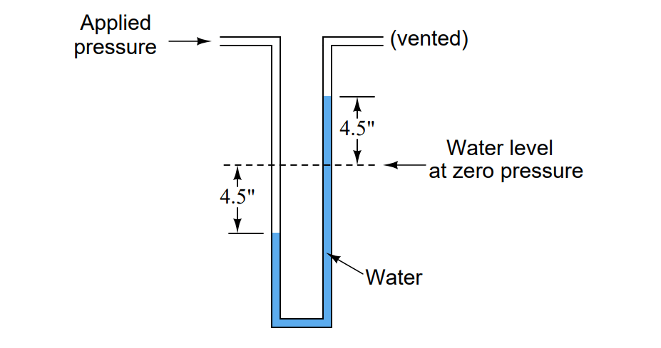
Pressure is set by the reservoir, specifically by the spring or weight loading its moving board divided by that board’s area. It is essentially independent of how many pipes are playing (that is the reservoir’s whole point). Pressure fixes two things the listener cares about:
- Loudness. A pipe voiced for a given pressure speaks louder when driven harder; higher wind pressure across a rank makes it louder. This is why loud, outdoor instruments (band organs) run higher pressures than intimate indoor ones.
- Pitch and tone stability. A flue pipe’s pitch and timbre both shift with the pressure driving its jet. Raise the pressure and the jet velocity rises, the pitch tends sharp, and an over-driven pipe can over-blow to its octave; drop it and the pipe goes dull, slow to speak, or fails to speak at all. Voicing is done at a specific pressure; hold that pressure and the pipes stay true. This pressure–voicing coupling is why “constant pressure” is not a nicety but the precondition for the organ being in tune with itself (How Organ Pipes Make Sound, Vol 6; John Smith Universal, Vol 10).
1.3.2 Flow — volume of air per unit time
Flow is the volume of air per unit time the system moves, quoted in litres per second (L/s) or cubic feet per minute (CFM). It is set at the demand end: each sounding pipe draws a certain volume of air per second through its foot, and the total flow the system must supply at any instant is the sum over every pipe currently speaking. A single small flute pipe might draw well under a litre per second; a full chord across several ranks, with the big open basses speaking, can demand many litres per second at once.
The raiser must be able to supply the average demand indefinitely (or the reservoir slowly empties), and the reservoir must store enough to cover the peaks — the instant a large chord opens — until the raiser catches up. When flow demand exceeds what the chain can deliver, the reservoir empties faster than it fills, its board falls, the pressure sags, and the pipes go flat and quiet together: the organ is “out of wind.” It is heard worst on big sustained low-register chords, which combine the largest per-pipe consumption with the most pipes. Curing it is a matter of flow (bigger feeders/blower, bigger reservoir, fatter trunk), not pressure. Consumption, peak-vs-average demand, and sizing supply to it are developed in Vol 04.
1.3.3 Why the independence matters
Because the two are independent, they are diagnosed and fixed independently — a theme that recurs throughout the series:
- A pressure that reads correct at idle but sags under a chord is a flow problem (undersized raiser/reservoir/trunk, or a leak), not a spring problem.
- A pressure that reads steady but wrong (organ uniformly sharp or flat, or too loud/soft) is a pressure problem — re-set the reservoir spring/weight and re-trim the spill valve.
- A pressure that wavers in time with the pump or crank is a regulation problem — the reservoir is not buffering the raiser’s pulsation well enough (feeder phasing, weak reservoir, concussion bellows). This is the province of Vol 05 on steadiness.
The pressure-vs-flow characteristic below makes the independence concrete. A well-regulated system holds its set pressure essentially flat as flow demand rises — each additional pipe drawing air makes almost no difference to the pressure — right up to the point where demand meets the raiser’s maximum supply. Beyond that knee the reservoir can no longer keep up, the board falls, and the pressure collapses: the organ runs “out of wind.” Good design keeps the worst-case chord comfortably to the left of the knee.
1.4 Units and conversions
Because pressures are quoted in several unit systems across the literature, the series fixes its conversions once, here. The anchor identity is:
1 in H₂O = 25.4 mm H₂O = 249.1 Pa = 2.491 mbar ≈ 0.0361 psi (at ~20 °C).
The pascal (Pa = N/m²) is the SI unit; the millibar (mbar = 100 Pa = hPa) is convenient because organ pressures land in single- and double-digit mbar. Note how tiny these pressures are in absolute terms — even a high-pressure reed at 30 in H₂O is barely one-tenth of an atmosphere (1013 mbar), and a normal flue chorus is under 1 % of atmospheric. Organ wind is a whisper of pressure, precisely held.
Table 1 — 4. Units and conversions
| in H₂O | mm H₂O | Pa | mbar (hPa) | psi |
|---|---|---|---|---|
| 1 | 25.4 | 249 | 2.49 | 0.0361 |
| 2 | 50.8 | 498 | 4.98 | 0.0723 |
| 3 | 76.2 | 747 | 7.47 | 0.108 |
| 3.5 | 88.9 | 872 | 8.72 | 0.126 |
| 5 | 127 | 1245 | 12.45 | 0.181 |
| 8 | 203 | 1993 | 19.93 | 0.289 |
| 10 | 254 | 2491 | 24.91 | 0.361 |
| 15 | 381 | 3736 | 37.36 | 0.542 |
| 30 | 762 | 7473 | 74.73 | 1.084 |
(Conversions computed at 1 in H₂O = 249.089 Pa. Flow units for reference: 1 CFM = 0.4719 L/s, so 1 L/s ≈ 2.119 CFM.)
1.5 Typical pressures across organ types
What pressure an organ runs is a design choice bound up with its voicing, its scale, and where it is played. Small, intimate instruments run low pressures for a gentle, easily-controlled speech; large, loud, or outdoor instruments run higher. The table gives representative working pressures; individual instruments vary and a single large organ commonly winds different divisions at different pressures.
Table 2 — 5. Typical pressures across organ types
| Organ type | Typical wind pressure | Notes |
|---|---|---|
| Chamber / house / continuo organ | ~2–3½ in H₂O (≈ 50–89 mm; 5–9 mbar) | Gentle, indoor; easy control |
| Baroque church flue chorus | ~2½–4 in H₂O (≈ 64–102 mm; 6–10 mbar) | Classical voicing |
| Busker / small barrel organ | ~3–5 in H₂O (≈ 76–127 mm; 7.5–12.5 mbar) | John Smith Universal ≈ 5 in H₂O (see that dive, Vol 04) |
| Romantic / orchestral flues, chorus reeds | ~5–15 in H₂O (≈ 127–381 mm; 12–37 mbar) | Louder, symphonic |
| Fairground / band organ | ~8–15 in H₂O (≈ 203–381 mm; 20–37 mbar) | Loud, outdoor |
| High-pressure solo reeds (Tuba, State Trumpet) | ~15–50 in H₂O (≈ 381–1270 mm; 37–125 mbar) | Commanding solo stops |
The busker/crank-organ band that this series centres on sits at the low end, ~3–5 in H₂O — loud enough to carry outdoors from a small pipe count, low enough to be raised comfortably by hand or crank without a blower. The John Smith Universal’s ~5 in H₂O (127 mm ≈ 1.25 kPa ≈ 12.45 mbar) sits at the brighter top of that band, and is the number the small-scale worked examples throughout the series use.
1.6 Why constant pressure is the whole point
Pulling §3.1 and §3.2 together: the reason the reservoir, the regulation, the relief valve, the concussion bellows, and the generously-sized trunk all exist is to present the pipes with a pressure that does not move — neither with the pump stroke nor with the chords being played. An imperfect system lets pressure dip on note attack and recover, heard as a slight breathing or shake in the tone, and lets one pipe rob wind from another when both speak at once, so a melody note wavers when the accompaniment enters. On a hand-cranked organ the failure is stark: if the reservoir cannot flatten the feeders’ pulsation, the whole rank warbles in pitch and loudness in step with the operator’s arm — the tell-tale sound of a badly-winded barrel organ. The measure of a good wind system is precisely that the listener cannot hear the raiser in the sound at all.
A subtlety worth flagging now and developing in Vol 05: a little unsteadiness is often prized. A wind that is alive rather than dead-flat lends a gentle animation that many builders voice for; entirely rigid wind can sound sterile. The art is a controlled, small liveliness — and, at the extreme, the deliberately pulsating wind of a tremulant, which shakes the column on purpose for a vibrato. A busker organ, having no tremulant, fakes the effect instead with a rank tuned slightly sharp that beats against a unison rank (an undulating stop, like a Voix Céleste). Both the accidental and the deliberate versions of unsteady wind are Vol 05’s subject.
1.7 Roadmap to Vols 2–7
This volume has set the frame: wind is a held low pressure, not a puff; it travels a fixed chain from raiser to pipe; and it is specified by pressure (set by the reservoir, quoted in in H₂O/mm/Pa/mbar) and flow (set by the pipes, quoted in L/s/CFM) as two independent quantities. The remaining volumes open each stage of that chain:
- Vol 02 — Raising the Wind. The raiser stage: feeders and bellows (wedge/ cuneiform and multi-fold), alternation for a continuous supply, and every prime mover — hand, foot (the calcant/blower-boy), crank, falling weight, water engine, and the modern electric rotary/centrifugal blower.
- Vol 03 — Storing & Regulating. The reservoir/regulator: single-rise vs double-rise, weights vs springs, inverted (compensating) ribs for a flat pressure across the stroke, the floating-lid Schwimmer, and the relief/spill valve that caps the pressure.
- Vol 04 — Pressure, Flow & Measurement. The water manometer; static vs dynamic pressure; wind consumption per pipe; why big chords sag; sizing the raiser, reservoir, and trunk to meet peak demand.
- Vol 05 — Steadiness & the Tremulant. Wind unsteadiness and shakes, robbing, concussion bellows/winkers; and deliberate tremulants (beating vs sinusoidal) — plus the busker organ’s slightly-sharp undulating rank.
- Vol 06 — Building & Troubleshooting a Small Wind System. Leather, gusseting, gluing, springs; sizing feeders and reservoir for a ~20-note organ; leak-finding; worked against the John Smith reservoir and band-organ practice.
- Vol 07 — Reference & Cheatsheet. The conversion table, wind glossary, formulas, materials/suppliers, bibliography, and a cross-index to Vols 1–6 and the sibling dives.
1.7.1 Cross-references
- John Smith Universal Organ, Vol 04 — Wind System — the concrete small-scale worked example: three 120°-phased feeders, a ~5 in H₂O sprung reservoir, spill valve, and manometer, built and dimensioned.
- How Organ Pipes Make Sound, Vol 2/6 — the pipe as the load at the end of the chain: how wind pressure sets jet velocity, and why pipes are voiced at a specific pressure.
- Vol 03 §on the regulator / Vol 04 §on measurement — where the pressure of §3 is set and read.
Sources
- Audsley, G. A., The Art of Organ Building (1905) — bellows, feeders, reservoirs, wind trunks; the ideal of a wind “absolutely steady” under all conditions of draw; the water-gauge convention.
- Pykett, Colin, pykett.org.uk — “The organ wind supply” and related articles on regulation, wind steadiness, and the reservoir as buffer between intermittent supply and intermittent demand.
- Organ Historical Society and standard organ-building texts — typical working pressures by organ type; the U-tube manometer as the reference instrument.
- Band-organ / mechanical-organ literature (COAA, Carousel Organ) and the sibling John Smith Universal dive — the small crank/busker case (~5 in H₂O), cited in full there.
Comments (0)