Wind Systems · Volume 2
Wind Systems — Vol 02: Raising the Wind
Vol 01 laid out the wind chain as a whole — raiser → reservoir/regulator → trunk → chest → pipe — and fixed the units and typical pressures. This volume treats the first link in isolation: the machinery that actually makes pressurized air. Everything downstream is storage, regulation, conveyance, and consumption; here the concern is generation. Two questions organize it. First, what is the pump — how does a feeder (a pumping bellows) convert reciprocating mechanical motion into a one-way stream of air, and why are feeders arranged to alternate so the stream is nearly continuous? Second, what drives the pump — the succession of prime movers, from the human arm and foot through the crank, the falling weight, and the water engine, to the electric rotary blower that displaced hand-blowing after about 1900.
Regulation — the reservoir that turns a pulsing feeder output into a steady set pressure — is Vol 03’s subject, and is treated there as a coupled spring-and-valve system. Measurement (the water manometer, static versus dynamic pressure, sizing supply to demand) is Vol 04’s. The concrete busker-organ realization — three feeders on a 120° crankshaft charging a sprung reservoir at 5 in H₂O (127 mm ≈ 1.25 kPa) — is worked in full in the sibling John Smith Universal, Vol 04; this volume states the general principle and cross-references that build rather than repeating its numbers.
Units note. Pressures are stated in inches of water gauge (in H₂O) with metric equivalents: 1 in H₂O = 25.4 mm = 249.1 Pa = 2.491 mbar ≈ 0.0361 psi (Vol 01 §units). Flow is stated as volume per time — litres per second (L/s) or cubic feet per minute (CFM); 1 CFM = 0.472 L/s. Figures the sources do not pin down are marked (est.).
2.1 The feeder: a one-way air pump built from bellows
A feeder is a bellows worked deliberately as a pump. Structurally it is the same object as the reservoir it charges — two boards joined by a flexible airtight gusset so the enclosed volume changes as the boards swing — but its function is opposite. The reservoir floats and stores; the feeder is driven through a stroke and delivers. What makes a bellows into a pump rather than a mere air-bag is a pair of one-way valves: an inlet valve that admits air on the opening stroke and seals on the closing stroke, and an outlet valve that seals on the opening stroke and passes air on the closing stroke. With that valve pair, the feeder’s back-and-forth motion is rectified into a one-way flow — exactly the function a check-valve pair performs for any reciprocating pump (Audsley, The Art of Organ Building, 1905, on feeders and their clacks).
2.1.1 The wedge (cuneiform) bellows
The classic feeder geometry is the wedge, or cuneiform, bellows: a single-fold form in which two roughly rectangular boards are hinged along one edge and splay apart at the other, so the air space is wedge-shaped and the whole thing opens and closes like a book. The three open edges are walled by the gusset — a strip of flexible material creased so it pleats inward as the wedge closes. In historical English and German organ-building the wedge bellows (German Keilbalg, literally “wedge bellows”) was the universal feeder and, before the horizontal reservoir came into use, was also the store: a rank of large wedge feeders pumped by hand or foot fed the wind trunks directly, which is why old organs “breathed” so audibly (Audsley; Organ Historical Society, historical bellows notes).
The gusset is the part that determines a feeder’s life and efficiency. It must be airtight, fold cleanly, and not billow. Leather — traditionally thin, supple sheepskin or the “alum-tawed” skins used across organ-building — is the standard; it is glued to the boards and reinforced at the corners, where three fold lines meet and where a gusset first splits (Audsley). At the small busker scale, coated domestic cloth substitutes for leather (John Smith Vol 04 §2.1). A limp gusset under load balloons outward on the pressure stroke and collapses inward on the suction stroke, wasting displacement and slapping audibly; the remedy, standard in the craft, is to glue thin internal ribs or stiffeners into the gusset so it folds along a controlled hinge instead of ballooning — set far enough from the crease that the fold can pleat freely, a point developed with the busker-scale build in John Smith Vol 04 §2.2.
2.1.2 The pumping stroke and the flap valves
The stroke has two phases, and the valves define which is which:
- Opening (suction) stroke. The boards are drawn apart, the enclosed volume grows, and the internal pressure falls below atmospheric. The inlet flap lifts and air is drawn in; the outlet flap is pressed shut by the pressure difference (reservoir pressure above it, sub-atmospheric below), so no air is sucked back out of the reservoir.
- Closing (delivery) stroke. The boards are driven together, the volume shrinks, and the internal pressure rises. The inlet flap seats shut so air is not simply expelled back to the room; the outlet flap lifts and the charge is forced into the trunk or reservoir.
The valves themselves are the simplest possible check valves: a leather-faced flap hinged along one edge over a rectangular or round port, lying flat over the port under its own light weight (and sometimes a whisper of spring), lifting only in the passing direction. Organ-builders call them clacks, flaps, or flap valves; the leather is the seal and the wood or the port frame is the seat (Audsley; Pykett, pykett.org.uk, on feeder and reservoir valving). Because the flaps do the directional sealing, a feeder need not be airtight against back-pressure the way a reservoir must — its gusset only has to hold air long enough to move it through the outlet on each stroke.
2.1.3 Displacement, and why a feeder is sized for flow
A feeder delivers, per delivery stroke, an air volume equal to the swept volume of its boards — roughly the change in the wedge’s enclosed volume between fully open and fully closed. Its average flow is that swept volume multiplied by the stroke rate. This is the quantity that must be matched to demand: the sum of what all sounding pipes draw (Vol 04 treats consumption per pipe). Pressure and flow are independent — pressure is set later, by the reservoir spring or weight (Vol 03), not by the feeder — so a feeder is sized for volume per unit time, and a raiser is judged “adequate” when it can keep the reservoir topped through the worst-case demand of a full low chord without the reservoir emptying. A raiser that cannot is heard as the wind “sagging” on big chords (Vol 04). The two levers the builder has are swept volume (bigger boards or longer stroke) and rate (faster pumping), and there are limits on both: a hand-blower tires, a crank has an ergonomic cadence, and an over-large feeder is heavy to work and slow to fill.
2.2 Alternation: turning pulses into a near-continuous stream
A single feeder delivers only on its closing stroke; on its opening stroke it delivers nothing while it re-inhales. Its output is therefore a train of pulses with dead gaps between them. The reservoir exists precisely to bridge those gaps (Vol 03), but the less ripple the feeders hand it, the smaller and steadier the reservoir can be, and the less the delivered pressure breathes with the pumping. The classical remedy, older than the organ blower and still used at every scale, is to run more than one feeder in anti-phase so that one is always delivering while another is re-filling — alternation.
2.2.1 Two feeders in anti-phase (double-acting)
The minimal alternating arrangement is two feeders phased 180° apart: as one closes and delivers, the other opens and re-charges, so there is a delivery stroke for most of every cycle and the summed output never falls fully to zero (Audsley, on the double feeder; Pykett, on feeder pulsation). Historically this was realized as the double-acting feeder — two feeders sharing structure and worked by a single lever or crank so that one arm’s up-stroke is the other’s down-stroke. The fonema.se description of street-organ practice — “the bottom two wedges constituting a double-acting feeder with valves for the air into the top, spring-loaded reservoir” — is exactly this, and is the arrangement of the John Smith Basic 20-Note (Vol 04 §3.1): two feeders, two connecting rods, crank throws 180° apart, welded up on a jig so the anti-phase is exact.
2.2.2 Three feeders at 120° — the busker case
Adding a third feeder and phasing the three at 120° smooths the output further: as one feeder passes through the dead spot at the end of its delivery stroke, the next is already mid-delivery, so the summed feeder flow has a smaller ripple and never drops to zero within a revolution. This is the John Smith Universal’s arrangement — three feeder bellows on a three-lobed crankshaft, lobes 120° apart, one connecting rod each (Vol 04 §3.2, citing Beckman, Carousel Organ #31). It is the busker organ’s answer to the same problem a multi-cylinder engine solves with a multi-throw crankshaft: more, smaller, evenly-phased impulses sum to a flatter total than one large impulse. For a hand-cranked instrument the payoff is direct — less ripple into the reservoir means the reservoir spring and spill valve have less transient to absorb, and the delivered wind is steadier for the same cranking effort, so the listener cannot hear the crank in the pitch.
The crank is the natural prime mover for this because it is the phasing device: the lobes’ angular offset on a single rotating shaft mechanically enforces the 120° (or 180°) relationship, and the operator’s job collapses to turning the handle at a comfortable cadence — commonly of order 50–70 rpm for a busker organ (est.; John Smith Vol 04 and busker practice). The geometric layout of that crankshaft driving its feeders is drawn in John Smith Vol 04 §3.2; the diagram below instead shows the result — how the phased delivery pulses overlap in time to approximate a continuous supply.
2.3 Prime movers: what drives the feeder
The feeder is a pump; something must work it. The history of organ wind is largely the history of that prime mover — from muscle, through ingenious mechanical and hydraulic drives, to the electric motor. Each suited a different combination of pressure, flow, era, and setting.
2.3.1 The hand lever
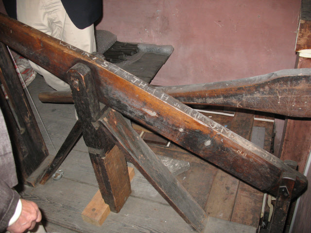
The oldest and simplest: an assistant works a lever (a “handle” or “pump handle”) that drives one or a pair of wedge feeders. On small chamber, chest, and continuo organs the hand lever survived into the modern era and is still fitted as a fallback. It suits low flow and modest pressure (chamber-organ pressures of roughly 2–3½ in H₂O; Vol 01) and one or two stops; a hand-blower cannot sustain the flow of a large chorus for long. It is silent electrically and independent of the mains — the reason a hand feeder is still valued for tuning, for recitals in buildings without power, and as a backup (Audsley; OHS).
2.3.2 The foot-pumped calcant (the blower-boy)
For larger instruments the blower stood on the bellows and worked them with body weight through foot treadles or a walking beam — the calcant (from Latin calcare, to tread), historically the “organ-blower” or “blower-boy”. Treading recruits the large muscles of the legs and the operator’s weight, so a calcant could raise far more wind than an arm at the lever, and a rank of large wedge feeders trodden in sequence gave the alternation of §2 directly. Bach’s and Handel’s organs were winded this way; a big instrument might need several calcants treading together. The trade was labour and cost: blowers had to be hired and paid, they tired, and their unevenness was audible — a standing motivation for the mechanical drives that followed and, ultimately, for the electric blower (Audsley; Pykett, on the pre-blower era; OHS).
2.3.3 The crank (busker and barrel organs)
On a self-contained street or barrel organ the same handle that drives the music also raises the wind: a crank turns a shaft whose throws (lobes) work the feeders. Because the crankshaft’s angular offsets fix the feeder phasing, the crank is at once prime mover and alternation mechanism (§2.2). It suits the busker scale — a few ranks, pressures of about 3–5 in H₂O (John Smith ≈ 5 in H₂O = 127 mm), modest flow — and the ergonomics of one person turning at roughly 50–70 rpm while also carrying the instrument’s weight. Its defining virtue is self-sufficiency: no assistant, no mains, no separate blower. Its defining limitation is that wind supply is tied to playing tempo, which is exactly why the reservoir and spill valve (Vol 03) must absorb the variation so the pitch does not follow the crank (John Smith Vol 04 §8).
2.3.4 The falling weight
A weight-driven engine stores energy in a raised mass and lets it fall to work the feeders (or, in the barrel-organ tradition, to turn the whole mechanism), much as a longcase clock is driven by its weights. It gives a smooth, even drive independent of a tiring human, but for a fixed store of potential energy — the weight must be periodically re-raised, and its run-time is limited by the drop available. Weight drives appear in automatic and clockwork organs and in some self-playing instruments rather than in large church organs, where the sustained flow needed would exhaust any practical weight far too quickly. They suit low, steady flow over a bounded interval (Audsley; OHS, on mechanical/automatic instruments).
2.3.5 The water (hydraulic) engine
Where a town had a pressurized public water main — many did in the nineteenth century — an organ could be winded by a hydraulic engine: mains water drove a piston or a set of bellows-actuating cylinders, and the exhaust water ran to drain. The water engine gave a tireless, even, on-demand drive that needed no blower to be hired and no weight to be re-raised, and it was widely fitted to Victorian church and concert organs between roughly 1850 and 1900. Its limitations were a dependence on adequate main pressure and flow, a running water bill, and — before careful governing — a tendency to draw more water than the utility liked. It was the immediate predecessor of the electric blower and, in many organs, was directly replaced by one (Audsley, on hydraulic engines; Pykett, on the transition to electric blowing; OHS). (Distinct from the ancient hydraulis, whose water column merely regulated pressure rather than driving the pump — a regulation topic, Vol 03.)
2.3.6 The electric rotary/centrifugal blower (since ~1900)
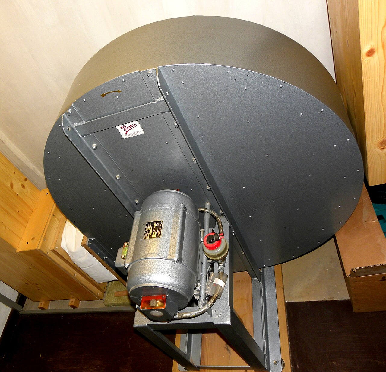
The decisive change came around 1900 with the small electric motor. Instead of reciprocating feeders and their valves, an electric blower uses a motor-driven rotating impeller — a centrifugal fan, or a stack of them in stages — spinning in a casing to raise air continuously to organ pressure. It has no pumping stroke and therefore no fundamental pulsation to smooth, no assistant to pay, no weight to re-raise, and no water bill; it runs at the flick of a switch for as long as the motor turns. Within about a generation it displaced hand- and foot-blowing on all but the smallest and the deliberately historic instruments (Pykett, on organ blowers; OHS).
Because the blower delivers continuously, it changes the raiser’s role: the reservoir no longer has to bridge the dead gaps of a reciprocating pump — it now mainly absorbs the mismatch between the blower’s steady output and the pipes’ fluctuating demand, and damps the blower’s own residual flutter. A blower is specified by exactly the two independent quantities of Vol 01:
- Pressure head — the static pressure it must raise, in in H₂O, set to a little above the organ’s working pressure so the reservoir and regulator have head to work against (a large romantic organ’s high-pressure reeds may demand 15–50 in H₂O; a small organ, 3–5 in H₂O).
- Flow (volume rate) — the air per unit time it must supply, in CFM or L/s, sized to the sum of the consumption of all pipes that can sound at once, with margin for the largest full-organ chord (Vol 04 develops the consumption sum).
A single-stage centrifugal fan raises modest pressure; higher organ pressures need multiple stages in series (each stage adds head) or a purpose-built high-pressure blower. Matching a blower to an organ is therefore a two-axis choice — enough head and enough flow — and under-sizing either axis is heard as the wind sagging under load, the same failure mode as an under-sized feeder (Vol 04).
2.4 Prime-mover comparison
The prime movers are best held side by side. The table summarizes era, the pressure and flow each suits, and the practical notes that decided which was used. Pressure bands follow Vol 01; flow “suitability” is relative (small organ = a few ranks; large = full chorus and reeds).
Table 1 — 4. Prime-mover comparison
| Prime mover | Era of chief use | Pressure suited | Flow suited | Notes |
|---|---|---|---|---|
| Hand lever | Antiquity → present (small organs, backup) | Low, ~2–3½ in H₂O | Low (1–2 stops) | Simplest; silent, mains-independent; blower tires; still fitted as fallback and for tuning |
| Foot calcant (blower-boy) | Antiquity → ~1900 | Low–moderate, ~2½–5 in H₂O | Moderate–high (recruits legs + body weight) | Winded large church organs; had to be hired and paid; unevenness audible; several treaders for a big organ |
| Crank (busker/barrel) | 18th c. → present (street organs) | ~3–5 in H₂O | Low (a few ranks) | Self-contained; the crankshaft also phases the feeders (alternation); supply tied to playing tempo — reservoir must absorb it |
| Falling weight | Automatic/clockwork organs | Low, steady | Low, over a bounded run | Smooth, even drive; limited by the drop; must be re-raised; suits self-playing instruments, not large organs |
| Water (hydraulic) engine | ~1850–1900 (Victorian organs) | Low–high (governed) | Moderate–high, on demand | Tireless and even; needs a pressurized main; running water bill; immediate predecessor of — and often replaced by — the electric blower |
| Electric rotary/centrifugal blower | ~1900 → present | Low → very high (multi-stage) | Low → very high (sized to demand) | Continuous — no pumping stroke to smooth; switch-on convenience; sized by both head (in H₂O) and flow (CFM/L·s⁻¹); displaced hand/foot blowing |
2.5 How the raiser hands off to the reservoir
Whatever the prime mover, the raiser’s output has the same character: a stream of air at a pressure and flow set by the pump and its cadence, still carrying some ripple (large from a single feeder, small from three phased feeders, smallest from a blower). That stream is delivered into the reservoir/regulator, the next link in the chain and Vol 03’s subject. The reservoir stores enough air to bridge the raiser’s gaps and to meet a sudden chord, holds the pressure close to a single set value through its spring or weight, and — with a relief/spill valve — caps the pressure by dumping any surplus the raiser delivers beyond what the pipes are drawing.
The division of labour is clean and worth stating as the handoff this volume ends on. The raiser makes the air — it sets how much flow is available and, through its cadence and phasing, how ripply that flow is. The reservoir conditions the air — it sets the pressure and smooths what ripple remains. A raiser sized for adequate flow with well-phased feeders (or a correctly sized blower) makes the reservoir’s job easy; a marginal raiser leaves the reservoir fighting a losing battle on every big chord, and the wind sags no matter how good the regulation. The two must be sized together, which is why Vol 03 (regulation) and Vol 04 (measurement and the consumption sum) follow directly from this one, and why the sibling John Smith Vol 04 treats its feeders, crankshaft, reservoir, and spill valve as a single coupled system rather than as separate parts.
2.5.1 Cross-references
- Vol 01 — The Wind Chain — the whole raiser → reservoir → trunk → chest → pipe chain; units (in H₂O / mm / Pa / mbar) and typical pressures by organ type.
- Vol 03 — Storing & Regulating — the reservoir this volume feeds: single- vs double-rise, springs vs weights, inverted/compensating ribs, the Schwimmer, and the relief/spill valve that caps the pressure.
- Vol 04 — Pressure, Flow & Measurement — the water manometer; the per-pipe consumption sum that sizes a feeder or blower; why big chords sag.
- John Smith Universal, Vol 04 — The Wind System — the concrete busker realization of everything here: three feeders on a 120° crankshaft charging a sprung reservoir at 5 in H₂O, with build detail and numbers.
Sources
- Audsley, G. A. The Art of Organ Building (1905; public domain) — wedge (cuneiform) feeder bellows and their clacks/flap valves; the double feeder and alternation; hand and foot (calcant) blowing; the hydraulic engine; historical wind-raising practice.
- Pykett, Colin — pykett.org.uk — feeder pulsation and valving; the pre-blower era and the transition to electric blowing; what an electric blower is and how it is characterized by pressure head and flow.
- Organ Historical Society (OHS) — historical bellows and blowing practice; calcants; automatic/weight-driven instruments; the adoption of electric blowers.
- fonema.se, Pushing and bouncing air — the street-organ double-acting feeder charging a spring-loaded reservoir; small-organ wind-raising layout.
- Beckman, Carousel Organ #31, and Senger, Carousel Organ #24–25 (COAA) — via the John Smith Universal dive: three feeders on a three-lobed 120° crankshaft; the double feeder at 180°; 5 in H₂O working pressure.
Comments (0)