Wind Systems · Volume 4
Wind Systems — Vol 04: Pressure, Flow & Measurement
Vol 01 established that a wind system is specified by two independent numbers — the pressure it holds and the flow it can supply — and deferred the question of how either is actually pinned to a figure. This volume answers it. It covers how pressure is measured, with the shop-standard water manometer as the reference instrument; the distinction between static pressure (read at rest) and dynamic pressure (read while pipes draw); how much air a pipe actually consumes, and why a big low chord is the worst case that makes an organ run “out of wind”; and how to size a small organ’s raiser, reservoir, and trunk to the demand it will see. The reservoir mechanism that sets the pressure is Vol 03; the steadiness of that pressure in time, and the tremulant that deliberately disturbs it, are Vol 05. This volume is about putting numbers on the wind — reading them off an instrument, and predicting when the supply will fail.
4.1 Measuring pressure: the water manometer
Organ wind pressures are so low — a few thousandths of an atmosphere (Vol 01 §4) — that the everyday pressure gauge is both too coarse and unnecessary. The reference instrument is a U-tube water manometer: a length of clear tube bent into a U, part-filled with water, with one leg connected to the wind and the other open to the room. It is cheap, needs no calibration, and reads the pressure directly in the units the trade quotes — inches or millimetres of water column. It is the tool every organ-builder and every busker-organ maker keeps on the bench (Audsley, The Art of Organ Building; Pykett, pykett.org.uk).
4.1.1 Why the water column is the pressure
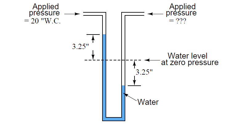
The manometer works because a stationary column of liquid balances a pressure by its own weight, with no moving parts to calibrate. When one leg is teed into the pressurized wind and the other is open to atmosphere, the wind presses down on the water in the connected leg and pushes it up the open leg until the weight of the raised column exactly balances the wind pressure. At balance, the pressure equals the hydrostatic head of the level difference:
p = ρ g h
where ρ is the density of water (≈ 998 kg/m³ at 20 °C), g is 9.81 m/s², and h is the difference in height between the two water surfaces. Rearranged, one millimetre of level difference corresponds to ρg × 0.001 m ≈ 9.79 Pa, and one inch to ≈ 248.6 Pa — which is why the “inch of water” (in H₂O) is defined as 249.089 Pa at a standard temperature and is used as an exact unit. The point of practical importance: the number the builder wants is already there on the ruler. There is no dial, no scale factor, no gauge to trust. The column is the reading. This is what “absolute” means in the sense used on the bench — not a vacuum reference, but a measurement that stands on physical constants rather than on a manufacturer’s calibration.
The figure below shows the standard arrangement: a U-tube teed into a wind trunk, with a worked reading of 5 in H₂O — the busker-organ pressure carried consistently through this series.
4.1.2 Reading it: a worked example at 5 in H₂O
Suppose the reservoir is set to the John Smith Universal busker pressure. Teeing a U-tube into the trunk and letting the levels settle, the water in the connected leg sits 127 mm below the water in the open leg. Read against a millimetre rule that is the pressure: 127 mm H₂O. Converting once, using the anchor identity of Vol 01 §4 (1 in H₂O = 25.4 mm = 249.089 Pa):
- 127 mm ÷ 25.4 = 5.00 in H₂O.
- 5 × 249.089 Pa = 1245 Pa = 1.245 kPa = 12.45 mbar (hPa).
- In old psi, 5 × 0.0361 = 0.181 psi — about one-fifth of a pound, a reminder of how gentle this pressure is.
The same reading in any of five unit systems, all consistent with the sibling John Smith Universal dive (Vol 04) and with Vol 01 of this series.
Table 1 — 1.2 Reading it: a worked example at 5 in H₂O
| in H₂O | mm H₂O | Pa | mbar (hPa) | psi |
|---|---|---|---|---|
| 1 | 25.4 | 249 | 2.49 | 0.0361 |
| 2 | 50.8 | 498 | 4.98 | 0.0723 |
| 3 | 76.2 | 747 | 7.47 | 0.108 |
| 3.5 | 88.9 | 872 | 8.72 | 0.126 |
| 5 | 127 | 1245 | 12.45 | 0.181 |
| 8 | 203 | 1993 | 19.93 | 0.289 |
| 10 | 254 | 2491 | 24.91 | 0.361 |
| 15 | 381 | 3736 | 37.36 | 0.542 |
(Computed at 1 in H₂O = 249.089 Pa, ~20 °C. Flow reference for later sections: 1 CFM = 0.4719 L/s, so 1 L/s ≈ 2.119 CFM.)
4.1.3 Practical notes on manometry
A few points decide whether the reading is trustworthy:
- Read the difference, not one leg. Only the difference between the two surfaces is the pressure. Reading a single leg against a fixed zero is wrong unless the other leg’s movement is negligible (true only for a large-bore reservoir well against a fine measuring leg). With two equal-bore legs, each surface moves half the total, so the 127 mm difference is 63.5 mm of drop in one leg and 63.5 mm of rise in the other.
- Parallax and meniscus. Read the bottom of the meniscus at eye level. A degree of colouring (a drop of ink) in the water makes the surface easier to see against a white card.
- Inclined and single-leg forms. For low pressures a leg can be laid at a shallow angle so that a small vertical head spreads over a long, easily-read slant length — an inclined manometer magnifies resolution (used where a few tenths of an inch matter). A well-type (single-leg) manometer reads directly because the large-area reservoir leg barely moves.
- Water versus oil. Water is the standard and defines the unit. A lighter oil (or coloured spirit) can be substituted for a more sensitive scale, but then the scale must be corrected for the fluid’s density — the reading is no longer “inches of water” until multiplied by the density ratio.
- Digital gauges (a piezo-resistive sensor reading in Pa or mbar) are convenient and read dynamic changes fast, but they are only as good as their calibration; the U-tube remains the absolute reference to check them against (Pykett).
4.2 Static versus dynamic pressure
Where and when the manometer is teed in changes what it reports, and confusing the two readings is a common source of false diagnosis.
Static pressure is the pressure of the wind at rest relative to the walls of the trunk or chest — the quantity that matters for voicing and loudness, and the one a manometer teed into the side of a trunk or into the chest reports. It is read with no pipe drawing (or teed at a point where the local air is not moving appreciably), and it is the number a reservoir is set to.
Dynamic (velocity) pressure is the additional pressure associated with air that is moving. In the trunk, wind flows only while pipes draw, and a manometer whose tapping faces into the moving stream will read the static pressure plus a velocity component ½ρv² (ρ here the density of air, ≈ 1.2 kg/m³); one facing downstream reads slightly less. Only a tapping flush with the wall, perpendicular to the flow, reads true static pressure while air moves. This is the same physics as a pitot-static tube used to measure airspeed, and it is why a wind-pressure tapping is always taken from a flush side-hole, never from a tube poked into the airstream (see the pitot-tube treatment in standard fluid-statics references).
For organ work two readings matter and they are usually taken at the chest, flush to the wall:
- Static, at rest (no note sounding). The set pressure — what the reservoir holds when nothing draws. On a well-regulated system this equals the design voicing pressure.
- Static, under load (pipes sounding). The pressure the pipes actually see while they draw. On a good system it is barely below the at-rest value; on an under-winded one it sags, and the size of the sag is the direct measure of the wind system’s adequacy. Reading both — quietly, then with a full chord held — and comparing them is the single most useful wind diagnostic on the bench.
The gap between those two numbers is the subject of the rest of this volume: it is set not by the pressure the reservoir can hold but by whether the chain can supply the flow the pipes demand while holding it.
4.3 Flow and demand: what a pipe draws
Pressure is set by the reservoir and is (ideally) independent of how many pipes play. Flow is set entirely at the demand end: each sounding pipe draws a volume of air per second, and the system must supply the running sum. This section puts numbers on that draw.
4.3.1 The flue as an orifice; pressure sets jet velocity
At a flue pipe’s foot the wind escapes through a thin slit — the flue or windway — as a fast, flat jet that strikes the upper lip and sets up the edge tone (How Organ Pipes Make Sound, Vol 2/6). The velocity of that jet is fixed by the pressure, through Bernoulli’s relation for air accelerated from rest across the flue:
v = √(2 p / ρ_air)
with p the wind pressure in Pa and ρ_air ≈ 1.2 kg/m³. At the busker pressure of 5 in H₂O = 1245 Pa:
v = √(2 × 1245 / 1.2) = √2075 ≈ 45.6 m/s.
So the jet at the mouth of a pipe on 5 in H₂O moves at roughly 46 m/s (about 100 mph) — the wind is a whisper of pressure but a brisk stream at the flue. Raise the pressure to 8 in H₂O (a band-organ figure) and the jet rises to √(2×1993/1.2) ≈ 57.6 m/s. This velocity is exactly the coupling between pressure and tone: a faster jet drives the pipe harder (louder) and shifts where it wants to speak (the pitch/regime, Vol 01 §3.1). Voicing is done at a chosen jet velocity, i.e. at a chosen pressure, which is why holding the pressure holds the tuning.
The volume flow a pipe draws follows from that velocity and the flue’s cross-sectional area:
Q = A_flue × v
A treble pipe with a flue slit of, say, 10 mm × 0.3 mm (area 3 mm² = 3×10⁻⁶ m²) passing a 46 m/s jet draws Q ≈ 1.4×10⁻⁴ m³/s ≈ 0.14 L/s ≈ 0.3 CFM. A large open bass, with a flue several times longer and wider, passes far more air at the same velocity because its slit area is an order of magnitude greater. The velocity is common to all pipes on one pressure; the consumption scales with flue area, which is why the big basses dominate the demand.
4.3.2 Approximate wind consumption per pipe
The numbers below are order-of-magnitude estimates (est.) — real consumption depends on scale, voicing, foot-hole and flue dimensions, and languid setting, and varies by well over a factor of two between builders. They are given to convey the ratio between a small treble and a big bass, not as spec values. They are derived from the Q = A_flue × v relation at ~5 in H₂O and are broadly consistent with the ranges organ-builders quote in CFM.
Table 2 — 3.2 Approximate wind consumption per pipe
| Pipe (flue) | Approx. flue area | Approx. draw (est.) | In CFM (est.) |
|---|---|---|---|
| Small treble (2′ stopped, ~C5) | ~3 mm² | ~0.1–0.2 L/s | ~0.2–0.4 CFM |
| Mid flue (~C4, 4′ range) | ~8 mm² | ~0.3–0.5 L/s | ~0.7–1 CFM |
| Tenor/bass flue (~C3, 8′) | ~20 mm² | ~0.8–1.5 L/s | ~1.7–3 CFM |
| Large open bass (16′, CC) | ~50 mm²+ | ~3–6 L/s | ~6–13 CFM |
| Small busker rank, ~20 pipes, few sounding | — | ~1–4 L/s | ~2–8 CFM |
| Church flue chorus, full, many ranks | — | tens of L/s | 100s of CFM |
The load spread is the headline: a single big bass can out-draw a dozen trebles. A rank’s worst case is not “all notes at once” evenly, but the specific chords that put several large pipes into play together. This is why blowers for full organs are rated in hundreds to thousands of CFM while a small busker organ is comfortably fed by a hand-cranked feeder set moving a few L/s on average (Pykett, “The physics of organ blowing,” on blowing power and consumption; band-organ practice).
4.3.3 Peak versus average, and why big low chords sag
Two different demand figures must both be met, by two different parts of the chain:
- The raiser (crank, feeders, or blower) must meet the average flow over time, or the reservoir slowly empties no matter how large it is. If the crank can deliver 3 L/s averaged over its rotation and the music sustains a 4 L/s draw, the reservoir loses 1 L/s of stored air until it bottoms out.
- The reservoir must cover the peak — the instantaneous surge when a large chord opens — for the fraction of a second before the raiser and the pallet flows settle. Its stored volume is the buffer between intermittent supply and intermittent demand (Vol 03).
When a big low chord opens — several large basses plus their upper ranks — the instantaneous demand can be many times the average, and if it exceeds what the reservoir plus raiser can jointly deliver, the reservoir board falls, static pressure sags, and every sounding pipe goes flat and quiet together: the organ is “out of wind.” It is worst in the low register for two compounding reasons — the big pipes each draw the most air, and low chords tend to use the most pipes (full registrations, pedal reinforcement). The manometer makes the failure visible: holding a full bass chord, the “static, under load” reading dips below the “static, at rest” reading, and the size of that dip is the wind system’s report card.
The figure traces static pressure against time as the organ is played: a single treble note barely disturbs it, but a sustained full bass chord pulls it down and holds it down until the chord releases — the signature of demand momentarily exceeding supply.
4.4 Sizing supply to demand for a small organ
Designing a wind system is choosing the reservoir spring/weight for the pressure (Vol 03) and the raiser, reservoir volume, and trunk area for the flow. The flow side comes down to three hedged rules of thumb; all are starting estimates (est.) to be checked against a manometer under a real worst-case chord, and all assume the small busker/barrel scale (~20 notes, one or two ranks, ~5 in H₂O).
- Raiser capacity ≥ sustained average demand, with margin. Estimate the average draw of the busiest passage the organ will actually play — for a ~20-note single or double rank this lands in the low single digits of L/s (say ~2–4 L/s est., ~4–8 CFM). Size the crank/feeder set (or blower) to deliver that plus roughly 50–100 % headroom so the reservoir refills between chords rather than trending empty. On the John Smith Universal this is met by three feeders phased at 120° on the crankshaft, arranged to overlap so delivery never falls to zero (John Smith Universal, Vol 04); the overlap converts three intermittent puffs into a near-continuous average (Vol 02).
- Reservoir volume ≥ the peak surge it must cover. The reservoir must give up enough air, at nearly constant pressure, to bridge the moment a full chord opens before the raiser catches up — a fraction of a second of the peak draw. As a hedged rule, a store holding at least a couple of seconds’ worth of the average draw (a few litres of swept volume on this scale, est.) rides over ordinary chord attacks; too small a reservoir and the pressure dips audibly on every attack (heard as the “breathing” of Vol 05), too large and the organ is slow to come up to pressure and bulky to build.
- Trunk cross-section generous enough that flow does not throttle it. A wind trunk is a pipe carrying air, and if the air must move too fast through it the velocity pressure (½ρv²) is spent as a pressure drop and the chest sags even while the reservoir reads correct (Vol 01 §2, trunk stage; §2 above on dynamic pressure). Keeping trunk air velocity modest — a common organ-builder target is to keep it well below ~8–10 m/s (est., varies by source) — sets a minimum cross-sectional area A ≥ Q_peak / v_max. For a peak of 4 L/s (0.004 m³/s) and a ceiling of 8 m/s, A ≥ 0.004 / 8 = 5×10⁻⁴ m² = 500 mm², i.e. a trunk of roughly 25 mm × 20 mm or a ~25 mm bore round hose as a floor, sized up for runs with bends. Undersizing the trunk is a classic hidden fault: the reservoir measures fine, but the chest starves.
The three ceilings interact: raising the pressure (louder) raises jet velocity and therefore raises the flow every pipe draws, so a louder setting needs a bigger raiser and fatter trunk as well as a stiffer spring. This is why the raiser, reservoir, and trunk are sized together against the same worst-case chord, and why the manometer — read at rest and under that chord — is the final arbiter that the sizing worked. The detailed dimensioning of a ~20-note system, with feeder and reservoir areas worked against the John Smith reservoir and band-organ practice, is Vol 06.
4.5 Pressure, loudness, and pitch stability
Tying the two quantities back together closes the volume. Pressure sets the jet velocity (§3.1), and jet velocity sets both loudness — a harder-driven pipe speaks louder — and the pitch/tone regime a pipe settles into. Flow determines only whether that pressure can be held while the pipes draw. The listener’s experience of a well-winded organ is the direct result: because the reservoir holds ~5 in H₂O flat against demand (Vol 03), every pipe finds its design jet velocity of ~46 m/s the instant its pallet opens, speaks at its voiced loudness, and holds its voiced pitch, whether it plays alone or in a full chord. When the wind sags — flow demand beating supply on a big low chord (§3.3) — jet velocity falls across the whole organ, and the pipes go flat and quiet together, the unmistakable signature of a wind, not a tuning, fault. A pipe that is flat only in company, never alone, is starved of flow, not mistuned; the cure is a bigger raiser, reservoir, or trunk (§4), never the tuning slide.
This is the through-line of the series stated in measurement terms: read the static pressure at rest and under the worst chord, and the two numbers tell the whole story. Equal numbers mean the wind is adequate and the pipes will hold their voicing; a gap between them is flow demand exceeding supply, quantified in inches of water on the same manometer that set the pressure in the first place. How that held pressure is made steady in the small-signal sense — freed of the pump/crank ripple and of pipe-to-pipe robbing — and how a tremulant deliberately disturbs it, is Vol 05.
4.5.1 Cross-references
- Wind Systems, Vol 01 §3–4 — pressure vs flow as independent quantities; the unit anchor (1 in H₂O = 249.089 Pa) reused here.
- Wind Systems, Vol 03 — the reservoir/regulator that sets and holds the pressure this volume measures (springs/weights, compensating ribs, spill valve).
- Wind Systems, Vol 05 — steadiness of the held pressure in time (robbing, concussion bellows) and the deliberate pulsation of the tremulant.
- Wind Systems, Vol 06 — dimensioning a ~20-note system’s feeders, reservoir, and trunk in full, worked against the John Smith reservoir.
- John Smith Universal Organ, Vol 04 — the concrete busker case: ~5 in H₂O, three 120°-phased feeders, sprung reservoir + spill valve, manometer on the bench.
- How Organ Pipes Make Sound, Vol 2/6 — the flue as the load: how wind pressure sets jet velocity and why pipes are voiced at a specific pressure.
Sources
- Audsley, G. A., The Art of Organ Building (1905) — the water-gauge convention; reservoirs, wind trunks, and the ideal of wind steady under all draw.
- Pykett, Colin, pykett.org.uk — “The physics of organ blowing” and “The organ wind supply”: blowing power, consumption, the reservoir as buffer between intermittent supply and demand, and the U-tube as the reference gauge.
- Standard fluid-statics / pitot-tube references — hydrostatic head p = ρgh fixing the water-column unit; static vs dynamic (velocity) pressure and why wind tappings are taken flush to the wall.
- Organ Historical Society and band-organ / mechanical-organ literature (COAA, Carousel Organ) — typical small-organ pressures and consumption; the U-tube manometer as the shop-standard instrument.
Comments (0)