Wind Systems · Volume 6
Wind Systems — Vol 06: Building & Troubleshooting a Small Wind System
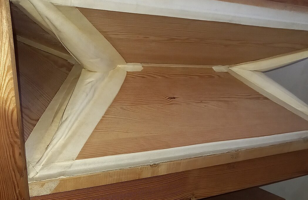
Vols 02–05 built the theory of the wind chain: how a feeder pumps (Vol 02), how a sprung reservoir stores and regulates (Vol 03), how pressure and flow are measured and matched to demand (Vol 04), and what makes wind steady or shaky (Vol 05). This volume is the workshop counterpart — the craft of actually making a small crank/busker-organ wind system that raises, holds, and delivers a flat column of low-pressure air. The worked scale throughout is a 20-note busker organ at about 5 in H₂O (127 mm ≈ 1.25 kPa ≈ 0.18 psi), with the concrete numbers, materials, and failures drawn from the John Smith range and cross-referenced to the sibling John Smith Universal, Vol 04 (Wind System) rather than duplicated.
The register here is deliberately narrow and practical: which leather in which weight, which glue for which joint, how to size the feeders and reservoir with headroom, and how to bring the finished thing up and chase the leaks that keep it from holding. The deep classic-vs-modern comparison of leathers, glues, and restoration philosophy is the subject of program Dive 15; where a full treatment belongs there, this volume gives only the working shortlist a builder needs at the bench.
Units note. Pressures are in inches of water column (in H₂O) with metric and psi equivalents; leather in decimal-inch thickness (the trade’s own unit) with millimetre equivalents; spring wire by diameter (mm / SWG). Figures the sources pin down are cited inline; anything estimated for the small-organ case is marked (est.) and never invented.
6.1 Airtightness is the whole game
A small wind system has exactly one hard requirement that dwarfs every other: it must be airtight where it is meant to be, and one-way-tight where a valve is meant to seal. Everything else — feeder displacement, spring force, trunk area — is arithmetic that a beginner gets roughly right on the first try. Airtightness is the part that separates a reservoir that floats and holds 5 in H₂O for a minute with the crank still, from one that collapses the instant pumping stops.
The reason is structural. The reservoir is not a pump — it has no stroke of its own; it floats on the balance between what the feeders deliver and what the pipes draw, held up by its spring (Vol 03 §1). A leak is therefore a continuous demand that never stops, exactly like a stuck-open pipe: it bleeds the store between feeder pulses, so the reservoir sinks, the pressure sags, and the operator has to crank faster just to stand still. A feeder, by contrast, tolerates a small skin leak because its flap valves do the sealing directionally and its stroke refreshes the charge many times a second — but a leaking flap is fatal, because a flap that will not seat lets the reservoir’s stored air blow straight back out through the feeder it just came from. So the two airtightness jobs are: the reservoir skin and its glue lines must not leak at all, and every flap valve must seat positively. The rest of this volume is, in effect, how to achieve those two things and then prove them.
6.2 Leather and cloth: what walls the bellows
The flexible walls (gussets) of feeders and reservoir, and the flap valves, are made of thin leather or coated cloth. Three material families cover the small organ.
6.2.1 Pneumatic and gusset leathers
The organ trade sells leather by function and weight, not by generic “thickness”. Columbia Organ Leathers — the reference supplier cited across the busker-organ community — grades its stock as follows (columbiaorgan.com):
- Gusset leather — the flexing walls of feeders and reservoirs. Columbia’s CPL White Gusset Leather is heavy African hairsheep with an applied white finish; CGL goatskin is the goatskin equivalent. John Smith’s plans specify Columbia CPL Gusset Medium for the bellows walls (Senger, COAA #24–25, via Universal Vol 04). Gusset leather is chosen supple enough to fold freely through the whole stroke without cracking.
- Valve leather — the facing of the flap valves. Columbia’s CGL goatskin valve leather is double-buffed: a velvety suede side that seats softly against the port and a de-glossed grain side that takes glue well. John Smith specifies Columbia CGL Valve-Heavy for the feeder flappers (Senger, COAA #24–25). The valve wants to be a touch heavier and stiffer than the gusset so it lies flat and seats by its own weight.
- Pneumatic leather — Columbia’s CML (maroon) / CTL (tan) hairsheep, processed to seal the pores and cut air porosity; medium runs ≈ 0.020 in (0.5 mm) and the heaviest ≈ 0.03 in (0.76 mm) (columbiaorgan.com). On a small organ this grade suits the reservoir skin, where low porosity matters most.
- Reservoir rib leather — pre-stretched hinge leather for the fold hinges and the fold-to-board attachments (columbiaorgan.com), so the folds do not creep as the reservoir cycles.
Leather thickness for busker bellows is a live topic on the Busker Organ Forum (tapatalk.com/groups/buskerorgan, “leather thickness”): the consensus is that a thinner, suppler skin folds with less resistance and steals less stroke than a heavy hide, so builders lean toward the lighter gusset weights for small feeders.
6.2.2 The economy substitute: blackout cloth
John Smith’s celebrated “readily-available-materials” ethos matters most here. His economy gusset is ordinary rubberised blackout curtain cloth — the coated domestic fabric — which is airtight, cheap, folds well, and brings a full organ into reach of a builder unwilling to buy hides (Senger, COAA #24–25; Melvyn Wright, John Smith pages, via Universal Vol 04). It has a real limitation: the coating is the seal, so a fold that flexes millions of cycles can eventually craze the coating along the crease, and cloth-only corners split where three fold-lines meet. The standard fix is to reinforce every corner with a small leather patch and to keep the folds controlled with internal stiffeners (§3). Leather gives the longest life and the best feel; blackout cloth gets a working organ built for the price of a curtain. The choice is a genuine trade, not a compromise to apologise for — the deep material comparison lives in Dive 15.
6.2.3 Bellows cloth proper
Between the two sits purpose-made rubberised bellows cloth (the reproducing- piano and reed-organ trade’s material), which is essentially the industrial version of the blackout-cloth idea: a woven fabric with an airtight rubber coat. It is the sensible middle choice for a builder who wants better longevity than curtain cloth without hide prices, and it glues and folds like the domestic substitute.
6.3 Gusseting and gluing the folds
6.3.1 Controlling the fold: stiffeners
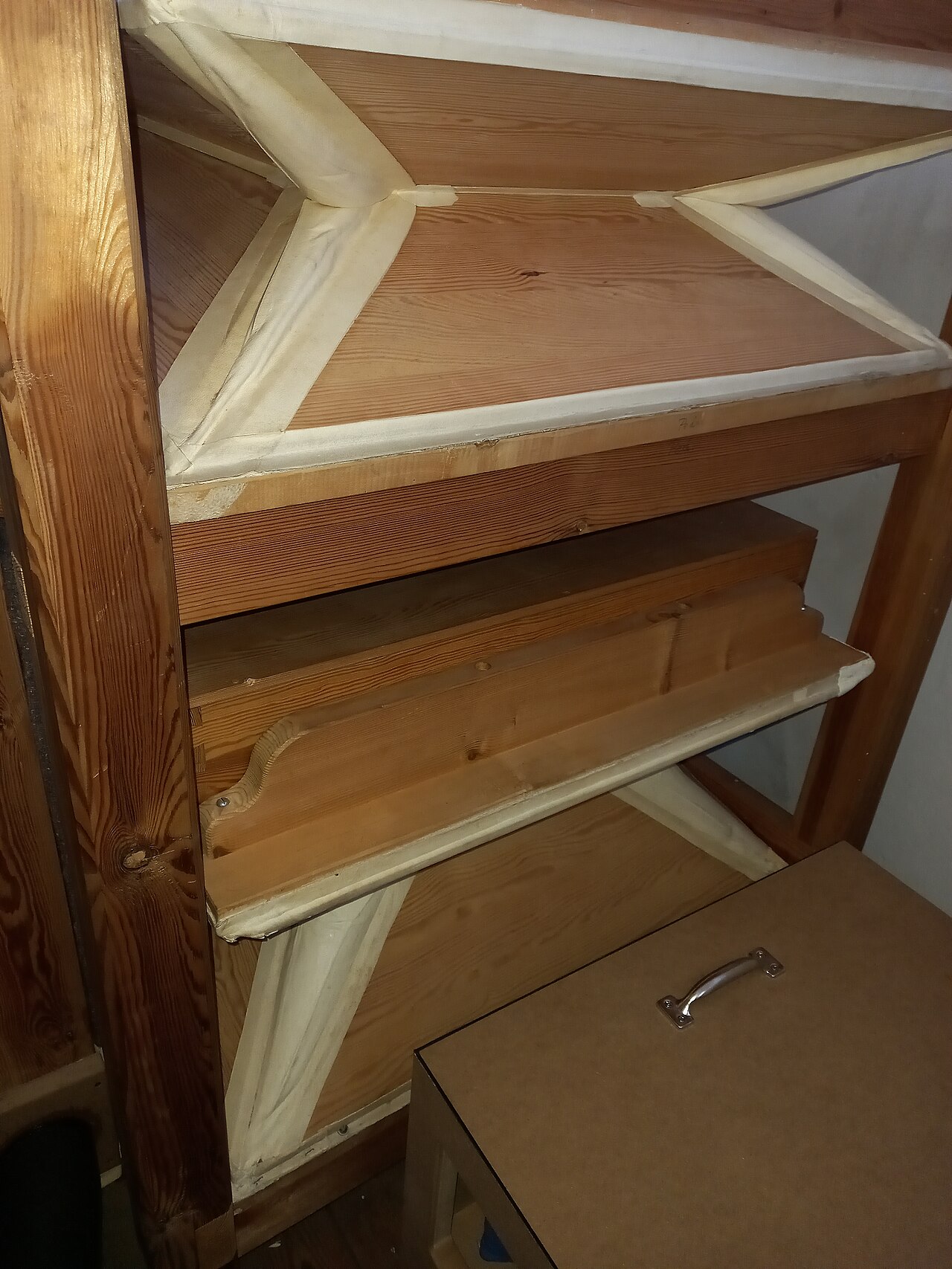
A gusset that is simply a limp wall will billow outward under pressure and suck inward under vacuum, wasting stroke and flapping audibly (Vol 02 §1.1). The standard organ-building fix is to glue thin internal stiffeners — light wooden ribs or stiff card — into the gusset partway up each side, so the skin pleats along a controlled hinge line instead of ballooning. On a wedge feeder there is one stiffener per side; on a multi-fold reservoir the fold hinges do the same job.
Warn — the fold-binding mistake. The classic beginner’s error is placing the stiffener too close to the fold (the moving hinge). When the bellows closes, a stiffener set near the crease jams against the opposing board or against the fold before the feeder has fully collapsed, so the boards bind: the stroke stops short, displacement is lost, and the crank develops a hard spot once per revolution. The stiffener must sit far enough from the fold that the skin can pleat around it freely through the whole stroke. This is the single most common cause of a stiff, short-stroking home-built feeder (Busker Organ Forum, bellows threads; Melvyn Wright; Universal Vol 04 §2.2).
6.3.2 Which glue for which joint
The glue is where airtightness is won or lost, and the busker-organ and restoration communities are unusually clear about the trade-offs (tapatalk.com/groups/buskerorgan, “quick glue experiment for bellows”; museumofyesterday.org; player-care.com). For the small builder the shortlist is:
- Hot hide glue — the professional’s choice for leather-to-wood. It forms a fully conforming, genuinely airtight joint, produces no bubbles, grabs fast, survives high humidity and heat once cured, and is reversible with hot water for future re-leathering (museumofyesterday.org; player-care.com). Its cost is process: it must be kept hot, and its short open time punishes slow work.
- Fish glue — John Smith’s specified adhesive for the leather-to-wood joints (Senger, COAA #24–25; Universal Vol 04 §2.1). Liquid and ready from the bottle, with a long-enough open time and useful cold tack that lets a soft skin be contoured around a corner. Its weakness is that it is hygroscopic — it draws moisture and, over years of damp storage, joints can weaken — so it trades some longevity for convenience (the English Woodworker; journeymansjournal). For a hobby organ kept indoors this is a reasonable trade, which is why the plans use it.
- PVA (white/yellow woodworking glue) — tempting because everyone has it, but the worst choice for a flexing airtight skin: it bubbles, dries slowly, is not reliably airtight by the way it cures, stays slightly flexible in a way that can creep, and — the restorer’s real complaint — will not stick to itself, so a future re-leather means scraping every trace off first (tapatalk.com/groups/ buskerorgan). Acceptable for board-to-board carcase joints; avoid it under leather.
- Hot-melt (glue gun) — fast and airtight in a bead, and it appears in quick-build accounts, but it is thick, leaves ridges under a thin skin that can telegraph as leaks, is not reversible, and softens with heat. Useful for tacking and for sealing a trunk joint; not the primary bellows adhesive.
The practical rule: hide or fish glue under all flexing leather/cloth; PVA only for rigid carcase joints; hot-melt for tacking and sealing, not for the folds. Whatever the adhesive, spread it thin and even — a starved or lumpy line is a future leak — and clamp or rub the skin down so no air is trapped beneath it.
6.4 Springs: setting the pressure
The reservoir’s pressure is the spring force on the moving board divided by that board’s area (Vol 03 §2). Three approaches serve the small organ, in ascending order of refinement:
- Office binder clip. John Smith’s famous economy spring: the sprung wire loops of an ordinary binder clip supply enough force on a small reservoir to reach working pressure (Senger, COAA #25; Universal Vol 04 §4.2). Crude but real, and infinitely available.
- A single heavy music-wire (spring-steel) spring bearing on the board — John Smith’s baseline (Senger, COAA #24–25). Simple, but its force changes as the reservoir moves through its travel, so the pressure is only approximately constant across the stroke.
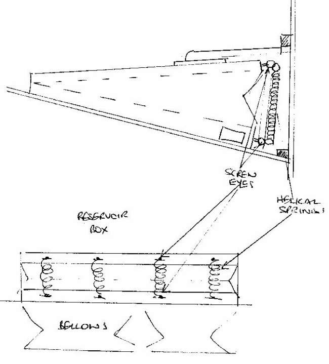
- Four small tension springs across the open end of the bellows — the widely recommended alternative (Melvyn Wright, reservoir-springs page). The pull is symmetric, the whole spring/reservoir assembly lifts out in one piece for service, and — the key steadiness trick — choosing longer, softer springs working over a small fraction of their travel keeps the force (and therefore the pressure) nearly flat across the reservoir stroke. This is the small-organ version of the compensating-rib idea from Vol 03 §3: make the loading force constant across travel.
Spring wire for a small reservoir sits in the ≈ 1.0–1.6 mm (roughly 20–16 SWG) range (est., scale it to the board area and target force); the honest method is not to calculate it but to tune it empirically against the manometer (§6), bending a leaf, adding or removing binder clips, or re-tensioning the four springs until the reservoir floats mid-travel at 5 in H₂O under a representative load, then trimming the spill valve to cap it there.
6.5 Sizing the feeders and reservoir for a 20-note organ
Sizing has one governing idea from Vol 04: the feeders must deliver, on average, at least the flow the pipes draw, and the reservoir must store enough to bridge the gaps and absorb the biggest chord. Both wanted with headroom, because a system sized exactly to demand has none in reserve for a fast passage, a leaky old skin, or a brisk full-organ finale.
6.5.1 Flow: how much air a 20-note organ actually wants
A 20-note busker organ rarely sounds all 20 pipes at once; typical polyphony is a melody note or two plus a bass note and an accompaniment chord — call it 4–6 pipes sounding on a busy beat. Small flue pipes at ~5 in H₂O each draw on the order of a fraction of a litre per second; a working planning figure for the whole small organ is roughly 1–3 L/s (≈ 2–6 CFM) peak (est., consistent with the small-organ demand discussion in Vol 04). The feeders must average this over a revolution; the reservoir must supply the momentary peak while the feeders catch up on the next stroke.
6.5.2 The feeder: displacement × strokes
Feeder output is swept volume per stroke × strokes per second (Vol 02 §1.3). The John Smith answer to smoothness is not a bigger feeder but more feeders, phased: the Basic 20 uses two feeders 180° apart (one delivers while the other refills); the Universal uses three feeders at 120°, so the summed feeder flow never drops to zero within a revolution and the reservoir has less ripple to absorb (Senger, COAA #24–25; Beckman, COAA #31; Universal Vol 04 §3). For a 20-note build, two feeders is the practical minimum and a comfortable cranking cadence (≈ 1–2 rev/s) with a modest per-feeder swept volume covers the 1–3 L/s demand with margin. Size the feeder so that at a relaxed cranking speed it already overfills the reservoir — the spill valve then dumps the surplus (§5.4), and the operator is never fighting the flow.
6.5.3 The reservoir: store enough to bridge and to absorb a chord
The reservoir’s stored volume must cover two things: the gap between feeder deliveries (fractions of a second) and the step demand of the biggest chord before the feeders respond. A reservoir whose moving board is comparable in area to the feeders and whose travel is a few centimetres stores ample air for a 20-note organ; the John Smith practice of a single reservoir sitting directly on the feeders (Senger, COAA #24–25; Universal Vol 04 §4.1) is the compact standard. Headroom rule of thumb: size the reservoir so a full expected chord drops the board by well under half its travel (est.) — if a chord bottoms the reservoir, it is too small or the feeders are not keeping up.
6.5.4 The spill valve: capping 5 in H₂O
Because the feeders are deliberately oversized, something must dump the surplus or the pressure would climb past the set point and the organ would sharpen and over-blow. That is the sprung spill/relief valve (Vol 03 §6): a leather-faced flap over a port, held closed by a light spring set so it seats at and below 5 in H₂O and lifts to vent the instant the reservoir tries to exceed it. The forces are tiny — on a 1 in (25.4 mm) port the face force at 5 in H₂O is only ≈ 0.14 lbf (0.63 N) (Universal Vol 04 §5), so a few ounces of spring holds it shut and a whisker more opens it. A travel-limit block bounds the board’s rise so it cannot over-tension its own spring. Spring (sets pressure), spill valve (caps it), and limit block (bounds travel) together hold the wind flat across the working range — the trio to get right on any small organ.
6.6 Materials shortlist
Table 1 — 6. Materials shortlist
| Item | Where used | Small-organ choice | Notes / source |
|---|---|---|---|
| Gusset leather | Feeder & reservoir walls | Columbia CPL Gusset Medium (or CGL goatskin) | Supple, folds freely; JS baseline (Senger #24–25) |
| Economy gusset | Feeder & reservoir walls | Rubberised blackout curtain cloth | Cheap, airtight; reinforce corners with leather (JS ethos) |
| Bellows cloth | Feeder & reservoir walls (middle option) | Purpose-made rubberised bellows cloth | Better life than curtain cloth, no hide cost |
| Valve leather | Feeder & spill flappers | Columbia CGL Valve-Heavy goatskin | Double-buffed; seats soft, glues on grain side (Senger #24–25) |
| Pneumatic leather | Reservoir skin (low porosity) | Columbia CML/CTL, ≈ 0.020 in (0.5 mm) | Pore-sealed hairsheep (columbiaorgan.com) |
| Rib / hinge leather | Fold hinges, board attachments | Pre-stretched reservoir rib leather | Resists fold creep (columbiaorgan.com) |
| Corner patches | Every bellows corner | Scrap leather offcuts | Where three fold-lines meet & first split |
| Reservoir spring | Sets the pressure | Music wire ≈ 1.0–1.6 mm (16–20 SWG) or 4 tension springs or binder clip | Tune to 5 in H₂O on manometer (Mel Wright; JS) |
| Primary glue | Leather-to-wood, flexing joints | Hot hide (best) or fish glue (JS spec) | Airtight & reversible; PVA not airtight |
| Carcase glue | Rigid board-to-board joints | PVA | Fine for wood-to-wood only |
| Sealing / tacking | Trunk joints, tacking | Hot-melt bead | Not under flexing leather |
| Hinges | Bellows board hinge edge | Leather hinge strip (or piano hinge on carcase) | Leather hinge is airtight and silent |
| Trunk / conveyance | Reservoir → chest | Flexible conduit / hose | Decouples vibration; JS uses flexible conduit (Senger #25) |
| Manometer | Setting & proving pressure | Clear U-tube + water + ruler | The reference instrument (Vol 04) |
6.7 Bring-up and leak-finding
6.7.1 First wind and the manometer hold test
The wind system cannot be set by feel; it is set against a water manometer — a clear U-tube half-filled with water (a drop of food colour makes the meniscus readable), teed into the reservoir output, read against a ruler in inches of water (Vol 04; organforum.com). The single most useful bring-up test is the hold test:
- Crank to a steady speed with no pipes speaking and read the pressure — it should sit at or a little above 5 in H₂O as the spill valve caps it.
- Stop cranking and watch the column. A sound reservoir holds pressure and sinks only slowly as the trapped air bleeds through whatever tiny leaks remain. A column that drops visibly in a second or two has a real leak to chase.
- Then crank with a representative chord sounding and confirm the column holds near 5 in H₂O without sagging — this proves flow, not just static tightness.
Tip — set and prove under load, not at idle. A system can read a perfect 5 in H₂O with the organ silent and then sag when a full chord opens if the feeders or reservoir are undersized or leaking. Always verify with pipes playing, and watch that the column holds steady rather than bouncing once per crank revolution — a bouncing column points straight at feeder phasing, a weak reservoir spring, or a leak (Universal Vol 04 §6).
6.7.2 The soap-bubble leak hunt
Once the hold test says there is a leak, find it. With the reservoir held under pressure (crank held, or a weight on the board), brush or spray dilute soapy water over every suspect surface and watch for growing bubbles — the workshop version of leak-testing a pressure vessel. Work the joints methodically: the glue lines where skin meets board, the corners, the fold creases (where blackout-cloth coating crazes), the flap-valve seats, the trunk connections, and any screw holes through a pressurised board. A stethoscope, or a length of hose held to the ear, will localise a hiss too small to bubble. Mark each leak, let the surface dry, and re-glue or re-seat it; hide and fish glue re-wet and take a patch cleanly, which is one more reason to have avoided PVA. Re-run the hold test after each fix — leaks are usually plural, and the biggest one masks the rest.
6.7.3 Chasing a sagging or shaking wind
Two failure feels recur once the gross leaks are out:
- A sag — the pressure droops on a big chord or a fast passage and recovers slowly. This is a flow problem, not a tightness problem: feeders too small or cranked too slowly, a reservoir too small to bridge, or a trunk too narrow and choking the delivery (Vol 04). The manometer confirms it — the column holds at idle but falls under load. Cure by sizing up (§5), not by hunting leaks.
- A shake — the pressure (and the pitch) pulses once per crank revolution. This is a regulation problem (Vol 05): too few feeders or bad phasing (a single feeder, or two throws not truly 180° apart), a weak or binding reservoir spring that cannot damp the ripple, or a spill valve fluttering because its spring is set right at the pressure. Cure by improving phasing, freeing or firming the spring, and — the classic damper — adding a small concussion bellows/winker tapped into the wind to absorb transient surges (Vol 05 §concussion bellows).
6.8 Troubleshooting: symptom → cause → fix
Table 2 — 8. Troubleshooting: symptom → cause → fix
| Symptom | Likely cause | Fix |
|---|---|---|
| Won’t hold pressure (column falls fast when cranking stops) | Skin/glue-line leak; split corner; unseated flap; leak at a screw or trunk joint | Soap-bubble hunt (§7.2); re-glue thin with hide/fish; patch corners; re-seat or re-face flaps; seal screw holes |
| Pressure sags on chords / fast passages | Feeders undersized or cranked slow; reservoir too small; trunk too narrow | Add/enlarge feeders; slow-crank still overfills? enlarge reservoir; open up the trunk area (§5) |
| Reservoir sinks / won’t rise to pressure | Spring too weak; binder-clip/leaf under-tensioned; big continuous leak masking it | Increase spring tension against manometer; clear the leak first, then re-tune |
| Pressure too high / organ sharp & over-blowing | Spring too strong; spill valve set too high or stuck shut | Ease spring; lighten spill-valve spring so it caps at 5 in H₂O; free a stuck flap |
| Wind shakes / pitch pulses once per crank rev | Too few feeders or bad phasing; weak/binding reservoir spring; spill valve fluttering | Improve feeder phasing (true 120°/180°); free or firm the spring; add a concussion bellows; re-set spill spring off the knee (§7.3, Vol 05) |
| Crank has a hard spot / feeder short-strokes | Stiffener too near the fold — boards bind (§3.1); connecting rod geometry cramped | Move stiffener clear of the fold hinge; check rod length/pivot so the stroke completes |
| Hisses / whistles under pressure | Small pinhole leak, crazed cloth coating along a crease, or a valve not lying flat | Localise with stethoscope/hose; patch skin; replace crazed cloth; re-lay or re-weight the valve |
| Held pressure but reservoir over-inflates / clatters | Missing or misplaced limit block; spill valve too small to vent surplus | Fit/adjust the travel-limit block; enlarge the relief port or soften its spring |
| Wind fine cold, leaks after storage | Fish-glue joints drawn moisture (hygroscopic); cloth coating perished | Re-glue affected joints (ideally hide glue); re-skin perished folds (see Dive 15 for materials) |
6.9 The measure of a good small wind system
A well-built small wind system is invisible in the sound: the pitch is steady, the volume even, and the pipes speak the way they were voiced whether the operator is cranking briskly or has slowed to talk to the crowd. That is bought with four cheap things done carefully — airtight glue lines under supple leather or coated cloth, stiffeners clear of the folds, a spring tuned on the manometer, and feeders sized with headroom — and proved with two simple tests: the manometer holds 5 in H₂O when cranking stops, and it still holds when a full chord opens. Get those and the wind system disappears, which is exactly what it is supposed to do.
6.9.1 Cross-references
- Vol 02 §1 — Raising the Wind — the feeder as a one-way pump, the wedge bellows, and the flap-valve stroke this volume builds.
- Vol 03 §2, §3, §6 — Storing & Regulating — spring-vs-weight loading, compensating ribs for flat pressure, and the relief/spill valve theory behind §4 and §5.4.
- Vol 04 — Pressure, Flow & Measurement — the manometer, wind consumption per pipe, and why big chords sag; the sizing arithmetic behind §5 and §7.
- Vol 05 — Steadiness & the Tremulant — robbing, shakes, and concussion bellows/winkers behind the “shaking wind” cure in §7.3.
- John Smith Universal, Vol 04 — Wind System — the sibling build-specific volume: three feeders on a 120° crankshaft, the reservoir/spring/spill-valve numbers, and the manometer tuning rig drawn on throughout.
- Program Dive 15 — Materials, Glues & Restoration — the deep classic-vs-modern comparison of leathers, cloths, and adhesives; this volume gives only the working shortlist.
Sources
- Columbia Organ Leathers (columbiaorgan.com) — gusset (CPL/CGL), valve (CGL goatskin), pneumatic (CML/CTL, ≈ 0.020–0.03 in), and pre-stretched reservoir rib leather grades and weights.
- Senger, Paul. “Building the John Smith Organ,” Carousel Organ #24 & #25 (COAA) — 5 in H₂O; CPL Gusset Medium / CGL Valve-Heavy leather; Fish Glue; double feeder + single reservoir; heavy music-wire spring and the binder-clip and blackout-cloth economy substitutes; flexible-conduit air hose.
- Beckman. “John Smith Universal (20/26) Organ,” Carousel Organ #31 (COAA) — three feeders on a three-lobed 120° crankshaft; sprung spill/relief valve.
- Melvyn Wright, John Smith Busker Organ pages (melright.com/busker) — bellows construction, the four-tension-spring reservoir alternative, and curing air leaks.
- Busker Organ Forum (tapatalk.com/groups/buskerorgan) — leather-thickness discussion; the stiffener-too-near-the-fold binding failure; the bellows glue experiment.
- Glue references — museumofyesterday.org and player-care.com (hot hide glue: airtight, reversible, humidity-/heat-resistant, no bubbles); the English Woodworker and journeymansjournal (fish glue hygroscopic; working properties); Busker Organ Forum (PVA not airtight, will not stick to itself).
- General organ-wind references (organforum.com; organsupply.com) — bellows leather/cloth practice and the U-tube water manometer as the reference pressure instrument.
Comments (0)