Wind Systems · Volume 3
Wind Systems — Vol 03: Storing & Regulating the Wind
Vol 02 delivered a supply of pressurised air: feeders — hand, foot, crank, weight, water engine, or an electric blower — raising wind and pushing it forward in intermittent, ripple-laden pulses. That raw supply is unfit to voice or tune against. Two jobs turn it into usable organ wind: storing it, so a momentary demand can be met from a local reserve rather than straight from the pump, and regulating it, so the delivered pressure holds close to one set value regardless of how fast the feeders run or how many pipes draw. Both jobs are done by one component family — the reservoir, also called the regulator or, at the small end, simply the bellows — and its associated relief/spill and cut-off valves.
The scope here is deliberately bounded. Measurement of the delivered pressure and flow (the water manometer, static vs dynamic pressure, sizing supply to demand) is Vol 04. The residual unsteadiness a real reservoir cannot remove — the breathing, robbing, and shakes, and the concussion bellows and tremulants that manage it — is Vol 05. The subject here is how the reservoir is meant to hold pressure flat; the sibling John Smith Universal, Vol 04 §4–5 works the same ideas at busker scale for one concrete build, and is cross-referenced rather than repeated.
Voice/units note. Pressures are stated in inches of water column (in H₂O) with mm, Pa/kPa, and mbar equivalents; 1 in H₂O = 25.4 mm = 249.1 Pa = 2.491 mbar ≈ 0.0361 psi (so 5 in H₂O = 127 mm ≈ 1.245 kPa ≈ 12.45 mbar ≈ 0.181 psi). Loads are in newtons and pounds-force, dimensions in mm. Unsourced figures are marked (est.) and never invented.
3.1 What the reservoir is for
A reservoir is “an enclosed space that not only acts as a storage space for wind from the blower, as its name implies, but also acts to control the pressure of the wind as it leaves” (Organ Historical Society, Organ Wind). Those are two distinct functions, and it is worth keeping them apart:
- Storage is a capacitance. The reservoir holds a volume of compressed air between the pump and the pipes, so a sudden draw (a full chord opening) is met first from the stored volume while the feeders or blower catch up. Without it, every demand transient would have to be answered instantaneously by the pump, which no hand-cranked feeder and no blower can do.
- Regulation is pressure control. A pump delivers whatever pressure the load and its own stroke happen to produce; the reservoir imposes a set pressure on the output and holds the delivered wind at that value across the working range of supply and demand.
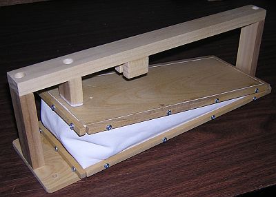
The classical arrangement, used from chamber organs to fairground organs, is a rise-and-fall reservoir: a box with a moving top board (the “lid” or “table”) that floats up and down, sealed to the fixed base by flexible folding sides. Air from the feeders inflates the box and lifts the lid; the pipes draw air out and the lid sinks; a loading force — springs or weights — bears on the lid and, divided by the area it acts over, sets the pressure. The reservoir position at any instant is a running average of supply against demand, and the loading force fixes the pressure at that position. The whole design problem of regulation reduces to one question: how to make that pressure the same at every lid position.
3.2 Loading the lid: springs vs weights, and what sets the pressure
The delivered pressure is, to first order, the loading force divided by the effective area of the moving lid:
$$ P \approx \frac{F_\text{load}}{A_\text{eff}} $$
For a lid measuring 300 mm × 450 mm (A = 0.135 m²), a target of 5 in H₂O (1 245 Pa) requires a net downward load of F = 1 245 × 0.135 ≈ 168 N ≈ 37.8 lbf — about 17 kg of dead weight, or a spring preloaded to that force. Push the same lid to a fairground 10 in H₂O (2 490 Pa) and the load doubles to ≈ 336 N ≈ 75.6 lbf. The rule that falls out of P = F/A is the one a builder uses at the bench: a heavier spring or weight raises the pressure; a lighter one lowers it, in direct proportion, for a given lid area. Halving the lid area at fixed load doubles the pressure. This is why organ pressure is set — not merely measured — at the reservoir, and why the pipes downstream inherit whatever number the loader is trimmed to.
The two ways to supply F behave differently across the lid’s travel, and the difference is the whole reason weights and springs are not interchangeable:
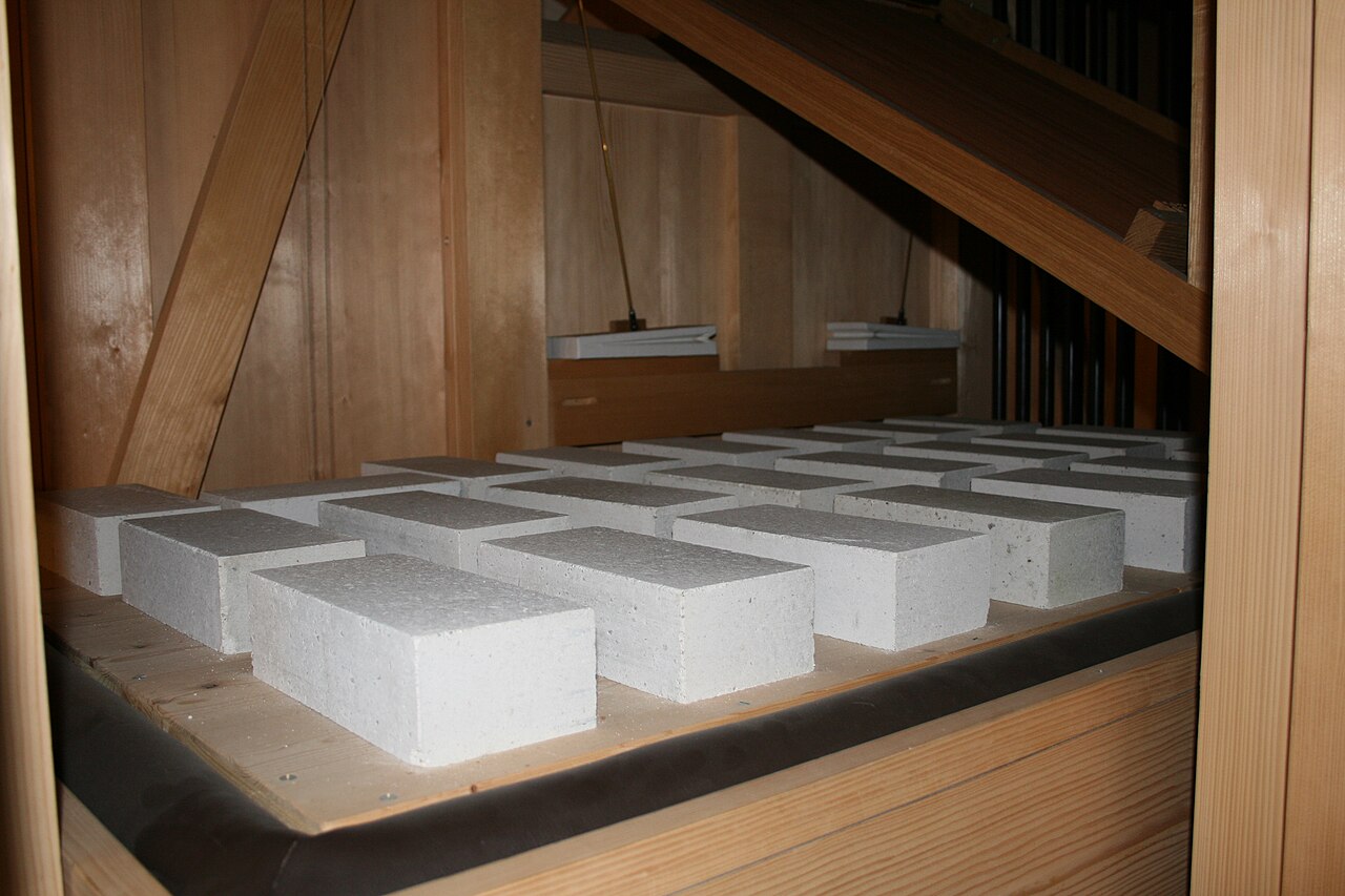
- Dead-weight loading supplies a force that is genuinely constant — a mass exerts F = mg whatever the lid height. If the effective area can be held constant (see §3), a weighted reservoir delivers a pressure that does not drift as it fills and empties. Weights are the traditional loader on large organs and band organs precisely because of this constancy; the drawback is bulk — a stack of iron or stone, or the reservoir itself hung upside-down so its own weight loads it. Audsley (The Art of Organ Building, 1905) treats the weighted rise-and-fall reservoir as the standard against which others are judged.
- Spring loading supplies a force that varies with compression: for a linear spring F = F₀ + k·x, so as the lid rises and the spring extends or compresses, the pressure ramps with it. Springs are compact, cheap, tunable by preload, and can pull as well as push, which is why every small crank and busker organ uses them (the John Smith Universal’s heavy music-wire spring — or its economy binder-clip — is the archetype; see John Smith Vol 04 §4.2). The penalty is that a spring reintroduces a position-dependent pressure even on a reservoir whose geometry is otherwise compensated. The mitigation is standard: use long, soft springs worked over a small fraction of their range, so k·Δx is small compared with F₀ and the force curve is nearly flat across the stroke (Pykett; Melvyn Wright, reservoir-springs page, cross-ref John Smith Vol 04 §4.2).
Pressure is therefore set by the loader, and its constancy across the stroke is a fight on two fronts: keeping the load flat (weights win) and keeping the effective area flat (the job of the ribs, next).
3.3 The key trick: inverted (compensating) ribs
A rise-and-fall reservoir cannot be sealed by rigid vertical walls — the lid has to move. It is sealed instead by ribs: hinged frames faced with airtight leather or rubber-cloth gusset that fold as the lid travels, like the sides of an accordion (OHS, Organ Wind, describes both “accordion fold lid” and rubber-cloth panel constructions). The ribs are what make regulation subtle, because an inclined, folding rib does not behave like a vertical wall.
3.3.1 Why a single rib course drifts
Consider the pressure balance again, P = F_load / A_eff. With rigid vertical walls, A_eff would simply be the lid’s plan area and, under a constant weight, P would be perfectly flat. But the folding ribs change that in two coupled ways as the lid rises:
- Projected area. The inclined gusset of a rib presents a horizontal projected area to the internal pressure. Part of the reservoir’s air load therefore reacts on the rib cloth, not the lid, and that projected area changes with the fold half-angle θ — which changes continuously as the reservoir opens and closes. So A_eff is not fixed.
- Rib thrust. The ribs also transmit force between lid and base at the fold angle; the vertical component of that thrust depends on θ as well.
In a reservoir with one course of ribs all folding the same way, both effects are monotonic in lid height: the pressure ramps steadily from one end of the travel to the other. An outward-folding course tends to make the pressure climb as the reservoir fills; an inward-folding course tends to make it fall. This is the well-known defect of the plain single-rise reservoir — it does not truly hold one pressure; it holds a pressure that walks up or down the stroke (Audsley; Pykett).
3.3.2 How inverting one course cancels the drift
The compensating trick is to run two rib courses whose folds oppose each other — one folding inward, one folding outward — either as the upper and lower halves of a single tall reservoir or as the two courses of a double-rise (§4). Because the two courses fold in opposite senses, as the lid travels the projected-area change of one course is equal and opposite to that of the other, and their rib thrusts likewise carry opposite slopes. The two contributions sum to a near constant:
$$ \frac{dA_\text{eff}}{dh} \approx 0 \quad\Rightarrow\quad P = \frac{F_\text{load}}{A_\text{eff}} \approx \text{const across the stroke.} $$
Stated in plain terms, the industry description is exact: the double-rise reservoir is “constructed with inward and outward folding ribs that stabilise the air pressure … one set of ribs folds outwards and the other folds inwards. This allows the top of the reservoir to move up and down without changing the outlet pressure” (Parkey OrganBuilders, Winding Systems; the same account appears in the mechanical-music literature, fonema.se / MMD). The outward course, whose pressure contribution rises with fill, is paired with an inward course whose contribution falls by the same amount; the ramps cancel. That geometric cancellation — not the spring, not the weight — is what makes the delivered pressure independent of how full the reservoir happens to be. The loader sets the level; the inverted ribs keep that level flat across the whole rise and fall.
3.4 Single-rise vs double-rise reservoirs
The number of rib courses distinguishes the two standard reservoir builds.
- Single-rise. One course of ribs; the lid rises and falls through one fold’s worth of travel. It is the simplest and most compact form and is common on small and older instruments. If the single course folds all one way it exhibits the pressure ramp of §3.1; makers who want a single-rise to hold pressure flat invert the ribs within the one course (top half out, bottom half in). Travel — and therefore stored volume — is modest.
- Double-rise. Two courses stacked with a floating intermediate frame between them, the upper course folding outward and the lower folding inward. This buys two things at once: twice the vertical travel (roughly twice the stored reserve for a given plan area) and, because the courses are inherently inverted with respect to each other, the compensating-rib pressure cancellation of §3.2 built in. The double-rise is the classical constant-pressure store of the church and concert organ, and of the band/fairground organ, where both a large reserve and a genuinely flat pressure are wanted (OHS; Audsley; Parkey). The cost is height, weight, and leather.
For the crank/busker scale this program centres on, a single spring-loaded bellows — effectively a small single-rise reservoir with a spill valve — is the norm, and the compensating-rib refinement is often dispensed with because the stroke is short and the spring is chosen soft (John Smith Vol 04 §4.1–4.2). Band organs, which run higher pressures (≈ 8–15 in H₂O) and much larger flows, move up to weighted double-rise reservoirs.
3.5 The floating-lid “Schwimmer” regulator
Modern small and unit organs frequently abandon the separate rise-and-fall reservoir in the wind line altogether and integrate the regulator into the underside of the windchest as a Schwimmer (German Schwimmer, “floater”). It holds pressure by an entirely different mechanism from the rib-compensated reservoir, and the contrast is instructive.
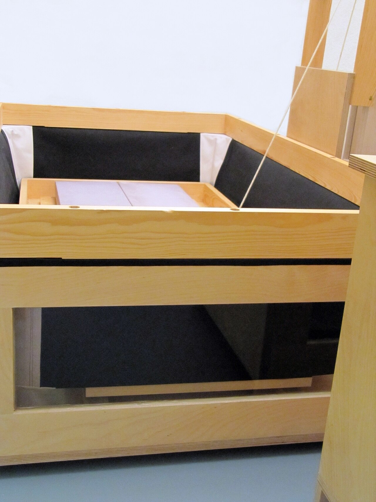
A Schwimmer is “a floating cut-out plate mounted with flexible leather, rubber or cloth” fixed directly to the bottom of the chest, so it “uses the windchest itself as the reservoir” (Parkey; OHS). Springs push the floating lid up (it hangs below the chest, so its travel is downward under demand, and the springs — not weights — provide the restoring force). Crucially, the lid is mechanically linked to an inlet valve: “when wind is consumed in the chest, the lid moves inward, under the tension of springs, and opens the inlet valve, admitting air from the blower. If the lid is large and the springs of the proper type, this kind of regulator produces the most stable wind pressure” (Wicks Organs, glossary).
In other words the Schwimmer is a proportional inlet servo, not a store: it holds pressure by continuously throttling the blower supply to match consumption, opening the inlet as the chest empties and closing it as the chest fills. Because it is the chest, it is compact, cheap, and — with a large lid and correctly chosen springs — extremely steady at static pressure. Its weakness is exactly its lack of a large stored reserve: the dynamic capacitance is only the chest volume, so it relies on a responsive blower behind it and can be prone to a low-frequency pumping oscillation (“Schwimmer bounce”) if the lid, springs, and blower are badly matched — a stability question deferred to Vol 05. The Schwimmer is therefore the blower-age counterpart of the weighted double-rise: the reservoir holds pressure by storing and compensating; the Schwimmer holds it by modulating the inlet.
3.6 Capping the pressure: relief/spill valves and the cut-off
The loader and the inverted ribs hold pressure flat only within the reservoir’s travel. Two failure modes lie beyond the ends of that travel, and each has its own guard.
Over-supply — the top of travel. If the feeders or blower deliver more air than the pipes consume, the lid rises to the top of its stroke and keeps being pushed against. Without relief, the loading spring compresses past its set point (or the ribs jam), pressure climbs, and the organ sharpens and over-blows. Two strategies bound this:
- A relief / spill valve vents the surplus. In its simplest small-organ form it is a sprung flap over a port in the reservoir: a leather-faced flap held shut by a light spring set so it stays seated at and below the target pressure and lifts to dump air the instant the reservoir tries to exceed it. The forces are small — for a 1-inch (25.4 mm) port, face area ≈ 0.785 in², the pressure face force at 5 in H₂O is only ≈ 0.14 lbf (≈ 0.63 N), so a few ounces of spring hold it (cross-ref John Smith Vol 04 §5, which works this valve in detail). The John Smith organ’s sprung-flap spill valve is the small-scale version of the relief function described here.
- A cut-off (curtain / trigger) valve throttles the supply instead of venting it. On blower- and larger feeder-fed organs the rising lid mechanically closes the inlet — a roller-blind “curtain valve” or a hinged trigger pallet linked to the lid — so that as the reservoir fills the supply is progressively shut off, and as it empties the inlet reopens. This is a servo, and it is more efficient than spilling (no air is wasted); the Schwimmer of §5 is the cut-off principle taken to its logical end, with the inlet valve being the regulator. Many reservoirs carry both: a cut-off for normal proportional control and a relief valve as a hard over-pressure backstop.
Collapse — the bottom of travel. The opposite fault is the reservoir running empty: if demand exceeds supply the lid sinks to the bottom, the spring or weight bottoms out, and the pressure falls away (the audible “running out of wind,” treated as a supply-sizing problem in Vol 04 and as a steadiness problem in Vol 05). A bottom stop or limit block prevents the ribs from collapsing flat and being damaged, but it cannot manufacture pressure — the real cure is adequate feeder/blower flow and enough stored volume, not a stop. The stop’s job is mechanical protection and defining the low end of the working stroke, so the lid floats between its limits rather than slamming either end.
Together the three elements bound the pressure from every side: the loader sets it, the inverted ribs hold it flat across the stroke, the relief/cut-off caps it against over-supply, and the bottom stop protects against collapse. A reservoir with all four keeps the delivered wind within a narrow band of one set pressure across the whole working range of supply and demand — which is precisely what the pipes downstream require and what Vol 04 will measure.
3.7 Regulator types compared
Table 1 — 7. Regulator types compared
| Regulator | How it holds pressure | Steadiness | Typical use |
|---|---|---|---|
| Single-rise reservoir | Loader (weight/spring) on a lid sealed by one rib course; stores a modest reserve. Pressure ramps slightly across the stroke unless the single course is internally inverted. | Moderate; flat only over a short travel, drifts with fill if ribs uncompensated. | Small chamber and older organs; the pattern behind the small sprung crank-organ bellows. |
| Double-rise reservoir | Loader on a lid sealed by two rib courses folding in opposite senses (inverted/compensating ribs); large stored reserve. Effective-area change cancels → flat pressure across a long travel. | High; genuinely constant pressure with a large dynamic reserve. | Church, concert, theatre, and band/fairground organs needing both reserve and flat pressure. |
| Schwimmer (floating lid) | Spring-loaded floating plate under the chest linked to an inlet valve; holds pressure by throttling the blower supply to match demand. Minimal storage (chest volume only). | Very steady at static pressure with a large lid + matched springs; small reserve, so transient dips and low-frequency bounce are possible. | Modern small, unit, and blower-fed organs where compactness matters. |
| Small spring reservoir / winker | Single sprung bellows storing a little air, pressure set by a soft spring, capped by a sprung spill valve. | Adequate at small scale and short stroke; some ripple passes through, damped by soft-spring choice. | Crank/busker and monkey organs (John Smith Universal, Vol 04). |
3.8 Where this hands off
This volume set the delivered wind to one flat pressure and stored enough of it to answer a transient. What remains is downstream:
- Vol 04 — Pressure, Flow & Measurement takes the manometer to the regulated output, distinguishes static from dynamic pressure, and sizes the feeder/blower flow and reservoir reserve to the pipes’ consumption — the “running out of wind” arithmetic this volume only gestured at.
- Vol 05 — Steadiness & the Tremulant takes up the unsteadiness a real reservoir cannot fully remove: the breathing on note attack, robbing between pipes, concussion bellows/winkers as fast local dampers, the Schwimmer-bounce resonance, and the deliberate pulsation of a tremulant (contrasted with the busker organ’s slightly-sharp undulating rank).
- The concrete busker-scale realisation of everything here — a single sprung reservoir at ≈ 5 in H₂O with a sprung spill valve, fed by three 120°-phased feeders — is worked end to end in John Smith Universal, Vol 04 §4–5.
The measure of a good reservoir is silence: the listener hears neither the pump behind it nor the demand in front of it, only pipes speaking at the one steady pressure they were voiced and tuned against.
3.8.1 Cross-references
- Vol 02 — Raising the Wind — the feeders, alternation, and blowers that charge the reservoir through its inlet.
- Vol 04 — Pressure, Flow & Measurement — measuring the regulated output; sizing supply and reserve to demand.
- Vol 05 — Steadiness & the Tremulant — residual unsteadiness, concussion bellows, Schwimmer bounce, and deliberate tremulants.
- John Smith Universal, Vol 04 §4–5 — the busker-scale reservoir, spring, and sprung spill valve worked as one concrete build.
Sources
- Audsley, G. A., The Art of Organ Building (1905, public domain) — the weighted rise-and-fall reservoir as the standard constant-pressure store; ribs, loading, and the single- vs double-rise distinction.
- Colin Pykett — pykett.org.uk — organ wind supply and regulation; soft-spring loading over a small stroke fraction for flatter pressure; wind steadiness.
- Organ Historical Society, Organ Wind (organhistoricalsociety.org) — the reservoir as store and pressure controller; accordion-fold vs rubber-cloth lids; springs or weights; the Schwimmer under the chest, moving down, spring-loaded.
- Parkey OrganBuilders, Winding Systems (parkeyorgans.com) — double-rise reservoir with inward- and outward-folding ribs, “top moves up and down without changing the outlet pressure”; box/wedge reservoirs; Schwimmer lids using the chest as reservoir.
- Wicks Organs, glossary — Schwimmer: floating lid linked to an inlet valve; large lid + proper springs → the most stable wind pressure.
- fonema.se, Pushing and bouncing air / Mechanical Music Digest — the double-acting-feeder + spring-loaded-reservoir layout of street/crank organs and the inward/outward compensating-rib account at small scale.
- John Smith Universal Organ, Vol 04 (Wind System) — sibling dive; the concrete busker reservoir, heavy spring, sprung spill valve, and ≈ 5 in H₂O working pressure.
Comments (0)