Encoding The Music · Volume 5
MIDI & Electronic Encoding
The perforated paper roll of Vol 4 stores the note-vs-time grid as holes in a strip of paper drawn past a tracker bar. This volume takes the same grid and replaces the paper with a file, and the tracker bar with a microcontroller. Nothing about the underlying abstraction changes — an organ still needs to be told which pitch, from here to there — but the carrier is now a stream of bytes and the reader is firmware. A MIDI file is the roll; a decoder board reads it and fires solenoid valves to open the pipes. The consequences ripple outward: the music library becomes weightless and unlimited, editing and transposition collapse to keystrokes, and the whole instrument gains a dependence on power, electronics and a bank of clicking coils that the paper roll never had.
The subject is the encoding and electronics principles: how MIDI encodes music, how a decoder turns a note-on into an open valve, how a fixed 20- or 26-note scale is mapped onto the 128 MIDI note numbers, and the practical solenoid driver, power and latency questions. The full MIDI-driven 20-note crank organ build is the subject of program dive 7 and is not pre-empted here; where the build has specific choices to make, this volume gives the general engineering and dive 7 gives the particular realisation.
5.1 MIDI as a notation: the file is the roll
The Musical Instrument Digital Interface, standardised in 1983 by the MIDI Manufacturers Association, was designed to let synthesisers and sequencers exchange performance data — not audio, but the events that describe a performance. That is precisely what a mechanical organ’s program is, which is why MIDI maps so cleanly onto it. Two facts make MIDI the natural digital form of the note-vs-time grid.
First, MIDI represents each note as a pair of discrete events rather than as a continuous mark: a note-on when the note begins and a note-off when it ends. The interval between them is the note’s duration — exactly the paper roll’s slot length, now expressed as elapsed time instead of paper distance. Second, MIDI’s note number is a discrete pitch index, one integer per semitone, which is the digital equivalent of the roll’s discrete tracker lanes. The grid survives the translation intact; only its physical spelling changes.
A Standard MIDI File (SMF, .mid) is the stored form. Internally it is a
sequence of delta-time / event pairs: each event carries the number of clock
ticks to wait since the previous event, then the event itself. Ticks are
converted to seconds through the file’s tempo meta-event (microseconds per
quarter note) and its division (ticks per quarter note, commonly 480 PPQN).
Format-0 files pack everything into one track; format-1 files keep separate tracks
that a player merges. For an organ, the SMF is read start to finish, each note-on
scheduled to open a valve and each note-off to close it — the file is the roll,
scanned by a clock instead of a spool.
5.2 Note-on, note-off, note numbers and channels
A MIDI message is one status byte followed by data bytes. Status bytes have their high bit set (values 0x80–0xFF); data bytes have it clear (0x00–0x7F), which is why every data value is capped at 127. The two messages that matter most for an organ are:
- Note-on: status
0x9n, then two data bytes — note number (0–127) and velocity (0–127). The low nibblenis the channel (0–15, presented to users as 1–16). - Note-off: status
0x8n, note number, release velocity. By a near-universal convention, a note-on with velocity 0 is treated as a note-off, which lets a stream of notes on one channel reuse the status byte (“running status”) for compactness.
The note number is the pitch. The convention is that middle C = 60, and
each unit is one semitone, so A440 (concert A above middle C) is note 69 and each
octave spans 12 numbers. The full range 0–127 covers roughly C-1 to G9 — far wider
than any organ needs, which is the point: a fixed-scale organ uses only a small,
specific subset (below). The formula is note = 12 x (octave + 1) + pitch_class,
with pitch class 0 = C; there is an old ambiguity over whether note 60 is labelled
C4 or C3, but the number 60 is unambiguous and is what the hardware acts on.
Velocity encodes how hard a key was struck — meaningful on a piano, largely irrelevant to a pipe that either speaks or does not. Most organ decoders ignore the velocity value and treat any note-on (velocity > 0) as “open this valve.” A few use it as a cheap on/off flag only, or to select between two ranks.
Channels are the second dimension an organ exploits. The 16 channels let one cable carry independently addressed streams. A common organ layout puts the melody and accompaniment pipes on one channel, the bass on another, and reserves further channels for percussion and registration: under General MIDI, channel 10 (index 9) is the percussion channel, where the note number selects a drum sound (35 = acoustic bass drum, 38 = acoustic snare, 42 = closed hi-hat, and so on) rather than a pitch. A decoder can watch channel 10 and fire a beater solenoid on the drum or a striker on a woodblock; it can watch a register channel and pull a stop or switch a rank on or off. The arranging implications — how many channels a 20-note scale actually needs, how percussion is voiced — belong to Vol 6.
5.3 The electrical layer: 31.25 kbaud serial
Classic MIDI is a deliberately cheap, robust serial link. The electrical specifics are worth stating because they set the timing floor for the whole system.
- Baud rate: 31,250 bit/s (31.25 kbaud), asynchronous serial, framed 8-N-1 — one start bit, eight data bits, one stop bit = 10 bits per byte.
- Each byte therefore takes 320 µs on the wire. A three-byte note-on (status + note + velocity) occupies 960 µs, roughly 1 ms; with running status, a note reduces to two bytes and about 640 µs.
- The physical layer is a 5 mA current loop, opto-isolated at the receiver so that ground loops between instruments cannot flow, historically on a 5-pin DIN connector. Modern builds usually carry the same 31.25 kbaud byte stream over a microcontroller UART, or wrap MIDI in USB-MIDI (USB packets, no 31.25 kbaud bottleneck), or read the SMF straight off an SD card so no serial link exists at all.
The 1 ms-per-note figure matters: it is the serial contribution to latency, and it is small compared with the mechanical delay of a solenoid (below). It also means a dense chord of, say, ten simultaneous note-ons is not truly simultaneous — the tenth note’s bytes arrive about 9–10 ms after the first — but for a hand-cranked organ playing human-tempo music this skew is inaudible.
5.4 From note-on to speaking pipe: the signal chain
The decoder’s job is to hold, at every instant, a picture of which note numbers are currently “on,” and to keep each corresponding valve energised for exactly as long as that note is held. The chain from stored program to sounding pipe has five stages.
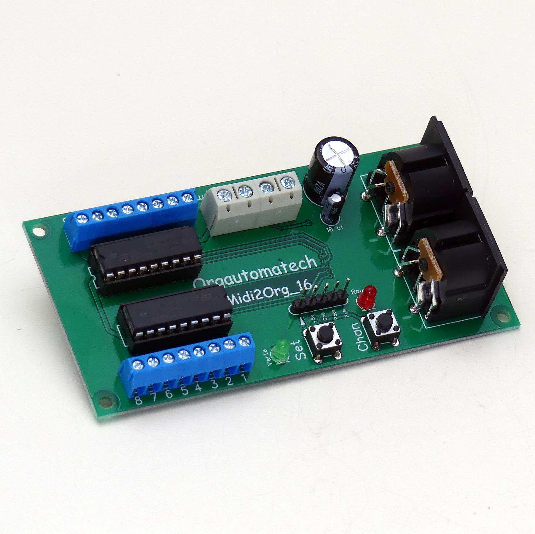
Stage 1, the source, is whatever supplies the byte stream: an SD card holding SMFs read directly by the microcontroller, a laptop or sequencer over USB-MIDI, or a live MIDI keyboard for playing the organ by hand. Stage 2, the decoder, is a microcontroller (an Arduino/AVR, a Teensy, an ESP32, or a Raspberry Pi Pico are all common in the community) running a small state machine: it parses each message, and on a note-on it looks the note number up in a scale map to find the output pin driving that pipe’s valve, sets that pin high, and remembers the note as “active”; on the matching note-off it clears the pin and the active flag. The map is the single most build-specific piece of firmware and is discussed next.
Stage 3, the driver, exists because a microcontroller pin can source only a few milliamps at 3.3 V or 5 V, while a solenoid coil wants hundreds of milliamps at 12 V or 24 V. A per-channel switching element bridges the gap (below). Stage 4 is the solenoid valve — a coil whose magnetic field pulls a plunger that lifts a pallet, uncovering the wind path to one pipe’s foot. Stage 5 is the pipe, which speaks for exactly as long as the valve is held open. The chain’s invariant, identical to every mechanical reader in Vols 2–4, is the note-on/note-off contract: open on note-on, close on note-off, duration equals the interval between them.
5.5 Mapping a fixed 20/26-note scale onto MIDI note numbers
MIDI addresses 128 pitches; a busker organ owns perhaps 20. The decoder must therefore hold a lookup table from note number to output — the digital equivalent of deciding which tracker-bar lanes exist and to which pipe each is plumbed. Only the note numbers that are physically wired respond; everything else is dropped or, by arrangement, folded into range.
The de-facto-standard Raffin 20-note scale spans roughly F3 to D6 as a gapped, F-major-ish set (essentially F major plus one E-flat, with no B natural anywhere), which lands on MIDI note numbers 53–86 — but not all 34 numbers in that span; only the ~20 that the scale actually contains are wired, and the accidentals it lacks have no pipe and no table entry. The exact hole-by-hole map, the missing B natural, and the 26-note Alderman extension are worked out in the sibling John Smith Universal dive, Vol 3; the point here is structural: the firmware table mirrors that scale one-to-one.
A representative fragment of such a table, in the spirit of the community’s decoders:
Table 1 — decoders
| MIDI note # | Pitch | Wired? | Output pin | Notes |
|---|---|---|---|---|
| 53 | F3 | yes | 0 | lowest bass pipe |
| 54 | F#3 | no | — | not in scale — dropped |
| 55 | G3 | no | — | not in scale — only three bass channels (F3, B♭3, C4) |
| 58 | A#3 / B♭3 | yes | 1 | bass B♭ |
| 59 | B3 | no | — | absent from the whole scale (no B natural) |
| 60 | C4 (middle C) | yes | 2 | |
| 63 | D#4 / E♭4 | yes | 4 | the one added flat (E♭, outside F major) |
| … | … | … | … | |
| 86 | D6 | yes | 19 | top melody pipe |
Two firmware policies handle out-of-scale notes. The strict policy simply ignores any note number with no table entry, trusting the arrangement (Vol 6) to have already removed unplayable pitches. A more forgiving policy folds an out-of-range note by octaves until it lands on a wired pitch, or snaps an unavailable accidental to the nearest wired note — useful when playing a general MIDI file live, but a blunt instrument that a proper arrangement makes unnecessary. Percussion and register channels (channel 10, and any reserved register channels) get their own small tables mapping drum note numbers or control events to beater solenoids and stop actuators.
5.6 MIDI note-on/off to valve timing, on the shared grid
Reduced to its timing, the whole system is one waveform: a MIDI note-on and its matching note-off bracket an interval during which the valve coil is energised and the pipe sounds. Laid onto the same pitch-vs-time grid used throughout this series (Vol 1), the electronic realisation looks identical to the paper roll’s slots — the marks are now current pulses.
The lower trace makes the mechanical reality visible: the coil does not switch instantly. On a note-on the current rises and the plunger takes a few milliseconds to pull in against spring and air load; on note-off it drops out over a similar interval. That mechanical delay, not the ~1 ms of serial transport, dominates the system’s latency.
5.7 Practical electronics: drivers, power, latency, noise
5.7.1 Solenoid drivers
Every valve coil is an inductive load switched on and off thousands of times an hour, so the driver stage has two jobs: provide the current, and absorb the inductive kickback when the current is interrupted. Two standard approaches dominate the DIY and small-commercial scene:
- Darlington array (ULN2803A / ULN2003A, or the TBD62003 MOSFET equivalent). A single chip — the 16-pin ULN2003A (seven outputs) or the 18-pin ULN2803A (eight) — provides open-collector Darlington outputs with the flyback (freewheeling) clamp diodes already integrated on-chip, which is why it is the community’s default recommendation — inexpensive (well under 1 USD) and wired in minutes (Yoctopuce, Building a MIDI automatic organ). It suits the ~100–150 mA valves typical of an organ.
- Discrete logic-level MOSFET per channel (e.g. an IRLZ44N or IRL520 as a low-side switch, with a ~220 Ω gate resistor and a discrete 1N4007 flyback diode across the coil, cathode to the positive rail). This is used when the coils draw more current than a Darlington array likes, or when PWM current-limiting is wanted (community MIDI-solenoid builds; Teensy/Arduino references). The flyback diode is not optional: without it, the coil’s collapsing field produces a voltage spike that will destroy the switching device.
Peterson pipe-organ solenoid valves, a common off-the-shelf choice, are commonly quoted (Busker Organ Forum) at about 90 Ω, drawing roughly 133 mA at 12 V — comfortably within a single Darlington channel; other valves and chest magnets differ, so the coil’s own resistance and rated voltage should be checked rather than assumed. A 20-note organ needs 20 such channels, plus a few for percussion and registers; three ULN2803A chips cover all 20 melody/bass valves.
5.7.2 Power
The logic and the coils want separate supplies with a common ground. The microcontroller runs on 3.3 V or 5 V at tens of milliamps; the valves run on a 12 V (or 24 V) rail sized for the worst-case simultaneous count. Twenty valves at 133 mA is 2.66 A, so a 12 V rail is specified with generous headroom (a 12 V, 5 A supply is typical) even though real music rarely holds all twenty at once. Because a solenoid dissipates power the whole time it is held, PWM hold-current reduction is a common refinement: drive the coil at full current for the few milliseconds of pull-in, then chop it down to the lower current needed only to hold the plunger, cutting heat and supply demand substantially on sustained notes. That trick belongs to the driver firmware and is one of the choices dive 7 makes concrete.
5.7.3 Latency
Total note-on-to-sounding latency is the sum of three terms: serial transport (~1 ms per 3-byte message, often zero when reading an SD card), firmware scheduling (sub-millisecond on any modern microcontroller), and solenoid mechanical pull-in (a few milliseconds up to ~10–20 ms depending on coil, spring and air load). The mechanical term dominates. As long as it is consistent across valves it is inaudible — a fixed offset shifts the whole performance, which a hand-cranked instrument absorbs invisibly. Trouble appears only if valves have different delays, smearing chords; matching valve types keeps the ensemble tight.
5.7.4 Valve noise and reliability
The step away from paper buys two liabilities. The first is acoustic noise: a bank of solenoids makes an audible mechanical click on every pull-in and drop-out, a percussive chatter under the music that purists count against the electronic organ and that careful mounting, damping and hold-current PWM only partly tame. The second is reliability surface: a paper roll has one moving part and fails gracefully (a tear, a jam) whereas the electronic organ adds a power supply, dozens of coils, driver chips, connectors and firmware, each a possible fault, and it will not play at all without power. Against these stand real gains — no paper to tear or damp, and a diagnostic advantage, since a stuck note is usually one identifiable channel to test rather than a mis-tracking mechanism.
5.8 Commercial systems and the DIY scene
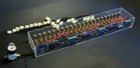
The MIDI organ is not a hobbyist curiosity; it is where the commercial busker and show-organ trade has largely moved. Raffin — whose 20-note (110 mm) and 31-note paper scales define the busker standard of Vol 4 — offers electronic, MIDI-driven versions of its portable organs alongside the roll-playing models, trading the spool box for an SD-card player and a solenoid chest. Wersi, long a maker of build-it-yourself electronic organs and digital instruments, sits at the fully electronic end of the same lineage. Retrofit interfaces to add MIDI to an existing roll organ are a recognised product category (e.g. Mike Knudsen’s published Build a MIDI Interface for the Raffin Crank Organ, COAA), and pipe-chamber control systems from firms such as Classic Organ Works productise the decoder-and-driver stage for larger instruments.

The amateur scene is deep and well documented. Melvyn Wright’s busker site carries a Adding MIDI to the Busker organ series; the Busker Organ Forum has long-running threads on making valves out of solenoids and on servo-versus-solenoid trade-offs; individual builders (e.g. Don Johnson’s MIDI busker organ) publish full construction logs; and general MIDI-solenoid tutorials using Arduino, Teensy and MOSFET or Darlington drivers are abundant. The common toolchain is a microcontroller reading SMFs from an SD card, a scale-map table in firmware, and ULN2803A or MOSFET driver boards into an off-the-shelf or home-made solenoid valve chest — precisely the architecture the dive-7 build follows.
5.9 Physical media versus MIDI: the trade-offs
The electronic medium wins decisively on library, editing and storage, and loses on power dependence, mechanical noise and cultural authenticity. The axes below summarise the choice a builder actually faces; the per-medium detail for the physical carriers is in Vols 2–4.
Table 2 — Physical media versus MIDI: the trade-offs
| Axis | Physical media (barrel / book / roll) | MIDI / electronic |
|---|---|---|
| Library size | One-to-a-few tunes per carrier; a repertoire is a shelf of barrels, a stack of books, or a box of rolls | Effectively unlimited — thousands of SMFs on one SD card |
| Editing / transposition | Slow and physical: re-pin, re-punch or splice; transposition means a new carrier | Trivial in software: edit events, transpose by adding a constant to note numbers, re-voice in seconds |
| Storage / weight | Bulky and heavy (barrels, crates of books); rolls lighter but still physical | Weightless — a memory card; the “roll library” is a folder of files |
| Power / electronics | None beyond wind; the roll/book itself needs no electricity | Requires a power supply, driver electronics and firmware; will not play without power |
| Authenticity / sound | The historically “authentic” medium; silent program, no coil chatter | Adds audible solenoid click; regarded by purists as less authentic despite identical pipe sound |
| Reliability | Few moving parts; fails gracefully (tears, jams) but the carrier is fragile (paper) or read-only (barrel) | More parts to fail (coils, drivers, PSU) but faults are localised and diagnosable; no paper to tear or damp |
| Cost | Low per carrier for rolls; high for pinned barrels; ongoing cost per tune | Higher one-off electronics cost; near-zero marginal cost per additional tune |
The historical trajectory of Vol 1 completes itself here: from the barrel’s read-only pinning, through the book’s re-punchable pages and the roll’s cheap home-punched paper, to a medium where the program costs nothing to copy and a keystroke transposes it. What the electronic organ trades away is not sound — the pipes are the same — but the silent, powerless, mechanical authenticity that made the paper roll of Vol 4 the sentimental favourite. Which side of that trade a builder takes is exactly the decision behind Jeff’s MIDI-driven 20-note build, taken up in full in program dive 7.
Sources
- MIDI Manufacturers Association, MIDI 1.0 Detailed Specification — message format (note-on 0x9n, note-off 0x8n), note numbers 0–127 with middle C = 60, velocity, 16 channels, General MIDI channel-10 percussion map, and the 31.25 kbaud / 5 mA current-loop electrical layer.
- Standard MIDI File (SMF) specification — delta-time/event structure, tempo and division (PPQN), format 0/1.
- Yoctopuce, Building a MIDI automatic organ, https://www.yoctopuce.com/EN/article/building-a-midi-automatic-organ — decoder architecture and the ULN2003A/ULN2803A/TBD62003 driver recommendation.
- Melvyn Wright, Adding MIDI to the Busker organ, http://www.melright.com/busker/jsart126.htm, and the Raffin pages, http://www.melright.com/busker/raffin.htm — busker MIDI practice and the Raffin electronic organs.
- Busker Organ Forum — “How I made valves out of solenoids,” “Solenoid or servo,” “MIDI Hand Crank Organ” threads (Peterson 90 Ω / 133 mA at 12 V valve figures; solenoid-valve construction).
- Mike Knudsen, Build a MIDI Interface for the Raffin Crank Organ, COAA (Carousel Organ Assoc. of America) journal — a published retrofit interface.
- Community MIDI-solenoid driver references (Arduino/Teensy, IRLZ44N/IRL520 MOSFET, 1N4007 flyback, 220 Ω gate resistor) — the discrete-driver stage.
- Q. David Bowers, Encyclopedia of Automatic Musical Instruments; MBSI / COAA journals — context for the busker/show-organ trade.
Cross-references: the paper-roll predecessor and its tracker-bar reading in Vol 4; the universal note-vs-time grid and the four-media overview in Vol 1; the concrete Raffin 20/26-note scale map, the missing B natural and the Alderman extension in the sibling John Smith Universal dive, Vol 3; arranging for the fixed, gapped scale (including percussion and register voicing) in Vol 6. Jeff’s full MIDI-driven 20-note crank organ build is program dive 7 — this volume covers the encoding/electronics principles; that dive covers the particular build.
Comments (0)