The Hobby Crank Organ · Volume 3
The Hobby Crank Organ — Vol 03: Anatomy & Build Sequence
Vol 02 fixed the Höffle 20-note organ as a design on paper: the 20-note Carl Frei
(Raffin/Stüber) scale, the four registers, and the ~60-page book that specifies
it (hobbycrankorgan.com/subdir/en_hoeffle.htm). This volume is the workshop
counterpart — the organ as an assembly of subsystems and the order in
which an amateur actually glues them up. Its evidence base is the two published
Höffle construction reports on the community site
(hobbycrankorgan.com/subdir/en_bouwhoeffle.htm and .../en_20Hoffle2.htm),
each a builder’s account of taking Walter Höffle’s plan to a finished, playing
instrument — one of them in about eight months of evenings
(.../en_bouwhoeffle.htm).
The register is deliberately practical: what stacks on what, which joint has to be airtight before the next one hides it, and which reading-and-valving parts are worth buying finished rather than making. It does not re-derive the wind theory (cross-ref the Wind Systems dive and John Smith Universal Vol 04), re-teach pipe-making (Vol 04 of this dive), or re-explain the music medium (Vol 05). Where a subsystem is treated in depth by a sibling volume, this one gives only the assembly-level view and points there.
Units and framing note. The Höffle is a pressure-wind pipe organ at the small busker scale — not the suction/“deairing” reed variant on the same site (
.../en_onderdruk.htm), and not a Brommer professional instrument. Wind pressure at this scale sits near 5 in H₂O (127 mm ≈ 1.245 kPa) — see the Wind Systems dive and John Smith Vol 04; this volume does not restate it. Dimensions from the construction reports are quoted as the builders give them (mm); anything inferred for the general hobby case is marked (est.) and never invented. Note count ≠ pipe count: 20 notes across four registers means many more than 20 pipes.
3.1 The organ as a stack of subsystems
A hobby crank organ is best understood not as a box of parts but as a short vertical chain of subsystems, each feeding the next, with the crank driving both ends of it at once. From the bottom up:
- The case / carcase — the structural shell and the acoustic floor. In the
reports this is birch plywood (12 mm) for the body, with a decorative
pinewood pedestal chosen “because of the decorative drawings of the grains”
(
.../en_bouwhoeffle.htm;.../en_20Hoffle2.htm). It carries every other subsystem, sets the standing space for the pipes, and closes into a portable, often cart-mounted, box. - The wind system — feeders (magazine bellows) that raise the wind and a sprung magazine/reservoir bellow that stores and regulates it to a flat pressure. Treated only at assembly level here; the full craft of leathering, gusseting, spring-setting, and leak-chasing is Wind Systems Vol 06 and John Smith Vol 04.
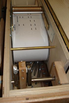
- The command block (wind chest + note valving) — the Höffle’s defining
part. It is the pressurised manifold that both reads the roll and admits
wind to the addressed note. The reports call it the command block or
playing table, and pair it with a pressure roller that holds the paper
against its reading face; both are “the most critical parts of this barrel
organ … Both parts are made of brass” in the original design
(
.../en_20Hoffle2.htm). - The register slides — one sliding bar per register, sitting over the pipe block, that admits or blocks wind to a whole rank at once so the operator can select which of the four registers speak.
- The drivetrain — the crank, which turns a feeder crankshaft to pump the bellows and, through a separate coupling, drives the music unit (the roll transport). One handle, two jobs. Assembly-level here; the crank/friction/idler detail is John Smith Vol 07.
- The music unit — the perforated paper roll (or cardboard book, or MIDI) and its transport: supply reel, take-up reel, and the coupling that advances it in step with the crank. The medium itself — making rolls, punching, scanning, MIDI — is Vol 05 of this dive.
The two ends of the chain are joined at the top: the register-selected pipes stand over the command block, fed by the wind the bellows raise and gated by the roll the same crank pulls. The exploded view below shows the relationship.
3.1.1 What is different from a valved John Smith organ
The Höffle’s signal architecture is worth contrasting with the sibling John
Smith Universal, because a builder who has read that dive will expect a
different layout. In the John Smith, the reading and the valving are separate
parts: a drilled tracker bar senses the roll and tubes each note down to a
pouch-and-pallet in a laminated pressure box (John Smith Vol 06). In the
Höffle, the reading face and the note valving are combined in one brass command
block pressed by a brass pressure roller — a more compact, more precise, and
less forgiving arrangement. The community reports treat the command block and
pressure roller as the two parts most worth buying finished, precisely because
their tolerances are the hardest to hit at home; the site sells both as ready-made
items (.../en_materiaal.htm: “Command block for 20 note Hoffle crank orgel”,
“Pressure roll for 20 note Hoffle crank orgel”). The admission logic itself —
a valve per note that lets wind into the addressed pipe, timed by the roll — is
the same principle treated in detail in John Smith Vol 06; this dive does
not re-derive it, and where a builder substitutes a home-made block the exact
internal valving is design-specific (est.).
The practical consequence of combining the two functions is that the Höffle has fewer parts and fewer tube runs than the valved John Smith, but less tolerance for error in the parts it does have. There is no forgiving pneumatic relay between the roll and the pipe: the reading face, the note channel, the register slide, and the pipe foot are a short, stiff, mechanical chain, and any slop or leak in it is heard directly. That is the trade the amateur accepts for the compactness of the design, and it is why the build sequence in §3 spends its discipline where that chain is assembled — Steps 3 and 4 — rather than on the wind system, which at this scale is arithmetic a beginner gets roughly right on the first try (Wind Systems Vol 06 §1).
3.1.2 The crank: one handle, two jobs
The single feature that most distinguishes a crank organ from a keyboard or foot-pumped instrument is that one hand turning one handle does everything — it must raise the wind and advance the music, continuously and in step, while the operator’s other hand is free to steady the organ or hold a hat out. The drivetrain therefore splits the crank’s rotation into two paths. The first path turns the feeder crankshaft, whose throws pump the feeder bellows on the wind side (§1, item 2); phasing multiple feeders around the crankshaft so their summed output never drops to zero is a wind-steadiness question handled in Wind Systems Vol 06 §5 and John Smith Vol 04. The second path drives the music unit — the take-up reel that pulls the roll across the reading face — through a separate reduction and coupling so the paper advances slowly and evenly regardless of the brisker feeder motion.
The reports show the coupling done simply: the paper drive engages the take-up
reel through “two pins … which interlock,” biased by “a small spring …
between the transmission wheel,” so the reel is positively driven in play but can
slip or disengage for rewind (.../en_20Hoffle2.htm). One builder’s
transmission uses a 5 mm drive cord off the crank line to turn the reel
(.../en_materiaal.htm). Getting these two paths to share one crank without a
hard spot or a tempo wobble is the assembly concern of Step 6; the friction,
idler, and take-up detail — including why a friction wheel that is not truly round
makes the music limp once per revolution — is John Smith Vol 07, not restated
here. The point at assembly altitude is only that the crank is a tee, not a
single line, and both of its branches must run sweetly before the case closes over
them.
3.2 The wind chest at hobby scale
At hobby scale the “wind chest” is the command block plus the pipe-block-and-slide assembly that sits on it. Its job is the whole point of the instrument: take flat pressure wind from the reservoir, and let it reach exactly the pipes the roll and the registers call for, at exactly the right instants.
3.2.1 The reading face and the note channels
The command block presents a row of fine holes on its top reading face, one
per note, on the note spacing. The perforated paper roll runs across this face,
held down by the pressure roller so the paper seals the holes it covers; where
a perforation registers over a note channel, that note is addressed and its pipe
speaks until the perforation passes and the paper re-seals the hole. The precision
that makes or breaks the organ lives here: the hole spacing must match the roll’s
track spacing exactly. One builder recut the block to his own 5 mm hole
centres across a 110 mm band rather than Höffle’s original 3.86 mm centres
— a deliberate, documented deviation that then required a matching roll and reel
(.../en_bouwhoeffle.htm). The lesson is that the command block, the roll, and
the punching all share one spacing standard and cannot be mixed.
3.2.2 The register slide over the pipe block
Above the note channels sits the pipe block carrying the pipe feet, and
between block and pipes run the register slides — the hobby-scale version of
the classic organ Schleife (slider). Each register (stopped flute, violin,
piccolo/open wooden) has its own row of pipes and its own slide. Pushed in, the
slide’s holes align with the note channels and the register’s pipes can speak;
pulled out, the slide’s solid web blocks them. That is how the operator turns
ranks on and off. The reports show a clean amateur execution: slides cut from
4 mm plexiglass running against plexiglas dams (no flannel), held down by
four slightly-loosened screws so the pipe block clamps the slide firmly enough
to seal yet leaves it free to slide (.../en_bouwhoeffle.htm). Wind reaches each
pipe foot through a conveyance tube — plastic hose “conically sharpened with
pencil sharpeners and press-fitted into 10 mm deep holes,” a cheap substitute for
the brass nipples of a costlier build (.../en_bouwhoeffle.htm).
The slides are what turn 20 notes into a varied-sounding organ. Höffle’s design
carries four registers — the stopped (gedeckt) flutes, the violin (string)
pipes, and the piccolo/open wooden pipes (.../en_hoeffle.htm; the per-register
pipe split is on the plan pages and is not restated here — mark any count (est.)
until read off the book, and note that 20 notes across four registers means far
more than 20 pipes). Each register is a full 20-note rank with its own timbre:
the stopped flutes are round and quiet, the strings keen and buzzy, the piccolo
bright and an octave up. By pushing and pulling the slides the operator combines
them — flutes alone for a soft passage, flutes plus strings for body, everything
drawn for a full chorus — so a single roll yields a range of registrations without
re-punching a note. At assembly altitude the slide’s job is binary and mechanical
(seal a rank in, block it out); the voicing and tuning that make the four ranks
blend, including the slightly-sharp rank some designs use to fake a tremolo, are
Vol 04 of this dive, not here.
3.2.3 Sealing the chest — the through-line
Everything the command block and pipe block do depends on their being airtight where they are meant to be, and this is the joint the whole build sequence is organised to protect. On a ~5 in H₂O organ the panels are barely stressed, but the chest is porous by a hundred small paths — a screw hole through a pressurised face, a channel that is not quite sealed to its neighbour, a ground-board seam glued proud on one edge, a conveyance-tube socket left loose. Each path lowers the pressure the addressed pipe sees, and a pipe run slightly low on wind speaks flat, late, and thin — a fault that looks like bad voicing but is really a leak one subassembly upstream (John Smith Vol 09).
The reports show the amateur’s sealing kit. The ground board (the underside face
that closes the valve box) is sealed with a “2 cm strip of leather as an air
barrier for the valve box,” and it is fastened with long screws into impact
(tee) nuts rather than wood screws — a small decision with a large payoff,
because it means the chest can be re-opened to reach a fault instead of being
glued shut forever (.../en_20Hoffle2.htm). Air ducts are extended off the box
with aluminium tube; note channels and duct holes are drilled halfway from
both sides after a 3 mm pilot and a Förstner counterbore, which the builder
credits with “perfect burr-free holes” — a burr in a wind channel both catches the
air and, at the reading face, can hold the paper off its seal
(.../en_20Hoffle2.htm). The discipline that ties §2 to §3 is simple: prove the
chest holds pressure while it is still open, before the pipes and then the case
bury it. A leak proved out on the bench is a five-minute reseal; the same leak
found after Step 5 means pulling pipes, and after Step 8 means a teardown.
3.3 The build sequence
The order of assembly is not a matter of taste; it follows the same two hard dependencies that govern any pressure-wind organ (John Smith Vol 09): some subassemblies bury others (once the pipes stand on the block there is no reaching the slides beneath them; once the case closes there is no reaching the wind chest inside it), and airtightness must be proved before it is sealed in (a leak found on the open bench is a five-minute fix; the same leak found after the case is glued is a teardown). The two Höffle reports differ in the details of their order — one built pipes first, the other bellows first — which is itself the lesson: the error-tolerant, cure-bound work goes early, and the parts that everything else is tested against or mounted on go in the middle.
A composite order that reconciles both reports:
- Case / carcase (rough). Build the structural shell from 12 mm birch
plywood, with the decorative pinewood pedestal and a stout base — one
builder used a 12 mm concrete-multiplex plate for the bottom to survive
transport (
.../en_20Hoffle2.htm). Rough, not finished: the case’s final internal width is only known once the wind chest and pipes are fitted, so decoration and final rip-to-width wait until Step 8. Airtight/aligned gate: the pipe-block seat and the wind-chest seat must be flat and square. - Wind system (feeders + reservoir). Leather the feeder bellows and the sprung
magazine/reservoir bellow, and prove them on the bench. The reports use
1 mm leather (one builder salvaged it from a sofa), 1.5 mm airplane
plywood stiffeners glued into the folds, a plywood template to mark and
cut the folds, and leather strips glued over the folds as combined hinge
and seal in place of metal hinges (
.../en_20Hoffle2.htm;.../en_bouwhoeffle.htm). The full craft is Wind Systems Vol 06 and John Smith Vol 04. Airtight/aligned gate: each feeder holds; the reservoir holds pressure with the crank still and its spill/overflow valve caps the pressure. One builder’s simple spill valve is “a square sheet of plywood, on which a strip of ragged leather is glued,” sealing a vent hole on the inside of the reservoir (.../en_20Hoffle2.htm). - Wind chest / command block + pallets. Fit (or make) the brass command block
and set its note channels on the roll’s exact spacing; skin the ground
board and seal it — one builder ran a “2 cm strip of leather as an air
barrier for the valve box” and used long screws with impact (tee) nuts
rather than wood screws so the chest can be re-opened
(
.../en_20Hoffle2.htm). Airtight/aligned gate: the chest holds pressure with the reading face sealed, and every note admits cleanly with no cross-talk between channels. This is the single most unforgiving joint in the organ; prove it with the chest still open (John Smith Vol 09). - Register slides. Fit the plexiglass slides over the pipe block against
their plexiglas dams, and set the four clamp screws so each slide seals yet
moves freely (
.../en_bouwhoeffle.htm). Airtight/aligned gate: with a slide pushed in, its rank’s channels are open and leak-free; pulled out, the rank is fully mute with no bleed past the web. - Pipework mounting. Stand the four registers of pipes on the block, each foot
over its channel, fed by the press-fit conveyance tubes. Mount them
removably so any pipe can come off for voicing or to reach the chest — the
reports secure the bass pipes with drilled wooden blocks on the base
(
.../en_20Hoffle2.htm). Voicing and tuning are deferred to Vol 04; here the pipes only have to seat, seal, and speak. Aligned gate: every pipe seats over its channel and lifts off without disturbing its neighbours. - Drivetrain / crank. Fit the crank, the feeder crankshaft that pumps
the bellows, and the coupling to the roll drive. The crank does both jobs; the
reports build the crankshaft to Höffle’s standard spec and couple the paper
drive to the take-up reel with “two pins … which interlock,” biased by “a
small spring … between the transmission wheel” so the reel can slip for rewind
(
.../en_20Hoffle2.htm). The friction/idler/take-up detail is John Smith Vol 07. Aligned gate: the crank turns without a hard spot, and the roll advances in step with the feeders. - Music unit. Fit the winding reels and roll transport. One builder turned
a reel from 100 mm PVC pipe with plywood-and-plexiglas disc sides, and used
Trespa for the reel-frame side walls because “the paper’s edge can be
extremely sharp” (
.../en_bouwhoeffle.htm;.../en_20Hoffle2.htm). The medium — books vs rolls vs MIDI, punching, scanning — is Vol 05. Aligned gate: a roll tracks true across the reading face with no wander. - Covering, finishing, and the cart. Only now, with the interior fitted, is
the case ripped to final width, decorated, and closed. The reports finish with
peasant-style painting (one used a soldering-iron burning technique with
carbon-paper transfer instead of paint) and build a cart with drawered
storage — one holds “8 drawers, whereby 5 music rolls can be stored in each
drawer … 40 rolls, more than 5 hours of varied music”
(
.../en_bouwhoeffle.htm;.../en_20Hoffle2.htm).
Two features of this order deserve emphasis because they are where first builds go
wrong. First, the case is deliberately split across Steps 1 and 8: rough shell
early (so the subsystems have something to be built on and referenced to), final
rip-to-width and decoration late (so the shell fits the interior that was actually
built rather than the interior on the drawing). Accumulated tolerance across pipes,
chest, and reels is real, and building the case oversize and trimming it to the
fitted assemblies absorbs that tolerance instead of demanding every part land on
nominal (John Smith Vol 09). Second, the airtight gates cluster on Steps 2–4,
the wind system and the reading-and-valving chain, because those are the
subassemblies that later steps bury. Once the pipes stand on the block (Step 5)
the register slides beneath them are hard to reach, and once the case closes
(Step 8) the whole interior is sealed away; a leak or a mis-registration caught on
the open bench costs minutes, and the same fault caught after burial costs a
partial teardown. The pipe mounting in Step 5 is therefore done removably on
purpose — drilled wooden blocks for the bass pipes, and mounts elsewhere that let
any pipe lift off — precisely so the buried chest stays serviceable
(.../en_20Hoffle2.htm; cf. John Smith Vol 09 §Phase 5).
That the two published reports disagree on pipes-first versus bellows-first is not a contradiction to resolve but the flexible part of the order made visible. Both reports agree on what cannot move: the wind chest must be proved airtight before the pipes go on it, the slides must seal before the pipes hide them, and the case must be trimmed to the fitted interior rather than the reverse. Within those hard dependencies, whether the builder spends the first weeks making pipes (the longest, most repetitive, most error-tolerant work) or leathering bellows is a matter of temperament and of which parts are in hand — either turns curing-glue dead time into progress while the hands learn the craft on forgiving parts before the unforgiving command block.
3.4 Materials shortlist (hobby scale)
The list below is the assembly-level shortlist a builder needs to start; it is not
a substitute for the Höffle book’s cut lists and drawings
(.../en_hoeffle.htm), and where a material is treated in depth elsewhere it
points there rather than duplicating. Bellows leather, gusseting, and glue
selection are covered in Wind Systems Vol 06; pipe woods are Vol 04 of
this dive. The site sells the two precision parts (command block, pressure roller)
and a short list of consumables finished (.../en_materiaal.htm).
Table 1 — 4. Materials shortlist (hobby scale)
| Item | Where used | Hobby-scale choice | Notes / source |
|---|---|---|---|
| Case body | Carcase, sides, lid | 12 mm birch plywood | Primed, base-coated, then decorated (.../en_20Hoffle2.htm) |
| Pedestal / trim | Base, decorative faces | Pinewood | Chosen for grain figure (.../en_bouwhoeffle.htm) |
| Case bottom | Transport-tough base | 12 mm concrete-multiplex | Survives knocks; carries bass-pipe blocks (.../en_20Hoffle2.htm) |
| Pipe wood | Four registers | Beech (Höffle’s plan: fir) | One builder swapped fir → beech for tone; see Vol 04 (.../en_bouwhoeffle.htm) |
| Command block | Reading + note valving | Brass (or beech home-made) | Buy finished; home-made in beech is a documented substitute (.../en_materiaal.htm; .../en_bouwhoeffle.htm) |
| Pressure roller | Holds roll to reading face | Brass | Bought finished; the other precision part (.../en_materiaal.htm) |
| Register slides | Rank selection | 4 mm plexiglass + plexiglas dams | No flannel; four clamp screws (.../en_bouwhoeffle.htm) |
| Feeder/reservoir leather | Bellows walls, hinges | ~1 mm leather; membrane < 0.5 mm | Salvaged sofa hide used in one build; membrane grade sold by the site (.../en_20Hoffle2.htm; .../en_materiaal.htm) |
| Fold stiffeners | Bellows folds | 1.5 mm airplane plywood | Glued into folds; cut to a plywood template (.../en_20Hoffle2.htm) |
| Bellows spring | Sets reservoir pressure | ~8 lb bellows spring | Sold by the site; tune on a manometer (Wind Systems Vol 06) (.../en_materiaal.htm) |
| Valve / spill leather | Overflow valve, pallets | Scrap / “ragged leather” strip | Simple spill valve on a plywood square (.../en_20Hoffle2.htm) |
| Conveyance tube | Chest → pipe foot | PVC hose (4 mm ID / 6 mm OD) | Cone-sharpened, press-fit into 10 mm-deep sockets (.../en_materiaal.htm; .../en_bouwhoeffle.htm) |
| Air-duct extensions | Ground-board runs | Aluminium tube | Extends ducts off the valve box (.../en_20Hoffle2.htm) |
| Reel body | Take-up / supply reel | 100 mm PVC pipe + ply/plexiglas discs | Turned reel; Trespa side walls (paper edge is sharp) (.../en_bouwhoeffle.htm) |
| Drive cord | Roll-drive transmission | 5 mm drive cord | Sold by the site (.../en_materiaal.htm) |
| Fasteners | Chest / housing (re-openable) | Impact (tee) nuts + long screws, M6 hex | Beat wood screws for repeated re-opening (.../en_20Hoffle2.htm; .../en_materiaal.htm) |
| Glue | Leather-to-wood, folds | Hide or fish glue (flexing joints); PVA for rigid carcase only | See Wind Systems Vol 06 §3.2 — not restated here |
| Air-barrier strip | Around the valve box | 2 cm leather strip | Seals the ground board (.../en_20Hoffle2.htm) |
3.5 Common build problems & fixes
The two reports and the site’s building notes (.../en_hoeffle.htm cites 8 added
pages of “building problems” in the book) surface a consistent set of failures.
Most are the pressure-wind organ’s universal faults — leaks, binding, cross-talk,
mis-registration — seen through the Höffle’s particular parts. The deep wind-side
troubleshooting is Wind Systems Vol 06 §8; this table is the whole-organ view.
Table 2 — 5. Common build problems & fixes
| Symptom | Likely cause | Fix |
|---|---|---|
| A note plays continuously (cipher) | Register slide not fully sealing; paper not seating on the reading face; a chest channel leaking to a pipe | Re-set the four slide clamp screws for firmer seal; check pressure-roller tension seats the paper flat; find the leaking channel and reseal (.../en_bouwhoeffle.htm) |
| A note runs on late / speaks weak or flat | Leak upstream (chest, ground board, trunk) starving the pipe; conveyance tube kinked or loose in its socket | Prove the chest airtight before enclosing (Step 3 gate); reseat the cone-sharpened tube in its 10 mm socket; chase the leak — it looks like bad voicing but is a leak (John Smith Vol 09) |
| A whole rank won’t turn on / won’t mute | Register slide hole spacing off; slide clamped too tight (binds) or too loose (bleeds) | Re-align slide holes to the note channels; back off / snug the four clamp screws so the slide seals yet moves (.../en_bouwhoeffle.htm) |
| Cross-talk — wrong pipe sounds | Command-block hole spacing does not match the roll’s track spacing | Match block, roll, and punch to one spacing (e.g. 5 mm vs Höffle’s 3.86 mm) — never mix standards (.../en_bouwhoeffle.htm) |
| Reservoir won’t hold / pressure sags | Bellows leak; spill valve set wrong; fold coating crazed | Soap-bubble hunt; reseal folds; set the ragged-leather spill valve to cap at working pressure (Wind Systems Vol 06 §7–8; .../en_20Hoffle2.htm) |
| Crank has a hard spot; feeder short-strokes | Fold stiffener too near the fold — boards bind; connecting-rod geometry cramped | Move the 1.5 mm-ply stiffener clear of the fold hinge; check rod length so the stroke completes (Wind Systems Vol 06 §3.1) |
| Burr-blocked / whistling air holes | Drilled holes left a burr that catches and leaks | Drill halfway from both sides after a 3 mm pilot and a Förstner counterbore for “perfect burr-free holes” (.../en_20Hoffle2.htm) |
| Roll wanders / paper edge cuts / tears | Reel side walls too soft or mis-aligned; take-up coupling slipping | Use hard Trespa side walls (sharp-edge safe); check the two-pin coupling and its slip spring engage cleanly (.../en_bouwhoeffle.htm; .../en_20Hoffle2.htm) |
| Case won’t close over the fitted interior | Case built to drawing before the chest/pipes were fitted | Build the case rough/oversize, fit the interior, then rip to final width (Step 1 → Step 8; John Smith Vol 09) |
| Chest can’t be re-opened to fix a fault | Assembled with wood screws that strip | Use impact (tee) nuts + long screws so the ground board and chest come apart again (.../en_20Hoffle2.htm) |
3.6 The measure of a good hobby build
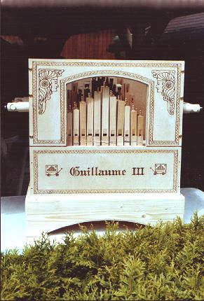
A well-built Höffle disappears into the music the same way a well-built wind system does (Wind Systems Vol 06 §9): the notes speak crisply on the beat, the registers switch cleanly, the crank turns evenly, and the roll tracks without a wander for its whole length. That is bought with a handful of cheap disciplines done in the right order — an airtight command block proved on the open bench, register slides that seal yet slide, conveyance tubes seated in clean burr-free sockets, a wind system tuned to a flat pressure, and a case ripped to fit the interior rather than a drawing. The two construction reports are, between them, proof that an ordinary person working evenings can reach that standard from Höffle’s ~60-page book; the value of the sequence in §3 is that it keeps every joint reachable and provable until it has earned the right to be hidden.
It is worth ending on what the reports also demonstrate about substitution,
because it is the amateur’s real freedom. Neither builder followed Höffle to the
letter: one swapped fir pipes for beech, brass command-block internals for beech,
and metal bellows hinges for leather strips; the other salvaged sofa hide for
bellows leather and replaced brass tube fittings with pencil-sharpened PVC hose
(.../en_bouwhoeffle.htm; .../en_20Hoffle2.htm). Every one of those changes
lands in the error-tolerant or cost parts of the organ — the pipe wood,
the case, the fittings — and none of them touches the two things that must be
right: the spacing standard shared by command block, roll, and punch, and the
airtightness of the wind chain from feeder to pipe foot. That is the useful
generalisation for any hobby crank organ, Höffle or otherwise: spend freedom on
the forgiving parts and discipline on the unforgiving ones, and build in the
order that lets the unforgiving ones be proved before they are buried.
3.6.1 Cross-references
- Vol 02 §2–3 — the Höffle 20-note design, the Carl Frei (Raffin/Stüber) scale, and the four registers this volume assembles.
- Vol 04 — Pipework the Hobby Way — making and voicing the stopped flute, violin, and piccolo/open wooden pipes mounted in Step 5; beech-vs-fir tone.
- Vol 05 — The Music Medium — the paper roll, cardboard book, and MIDI, the reels and punching fitted in Step 7; how the reading face is addressed.
- Wind Systems Vol 06 — Building & Troubleshooting a Small Wind System — the full craft behind Step 2 and the wind-side rows of §5: leather, gusseting, glue selection (§3.2), spring-setting, and leak-finding; not restated here.
- John Smith Universal Vol 04 — Wind System — the sibling build’s feeders, three-lobed crankshaft, reservoir, spring, and spill valve.
- John Smith Universal Vol 06 — Pressure Box, Tracker Bar & Valves — the canonical pouch-and-pallet note-admission action; the Höffle combines reading and valving in one brass command block instead.
- John Smith Universal Vol 07 — Drivetrain & Roll Transport — the crank, friction/idler drive, and take-up detail behind Step 6.
- John Smith Universal Vol 09 — Assembly Sequence — the sibling build order and the “prove it before you bury it” dependency logic this volume applies to the Höffle.
Sources
- Höffle construction report 1 (
hobbycrankorgan.com/subdir/en_bouwhoeffle.htm) — a builder’s ~8-month account: beech pipes in place of fir; leather-strip bellows hinges; birch-ply body and pinewood pedestal; command block recut to 5 mm hole centres (vs Höffle’s 3.86 mm) across 110 mm; 4 mm plexiglass register slides with plexiglas dams and four clamp screws; cone-sharpened PVC conveyance tubes press-fit into 10 mm sockets; 100 mm PVC reel; soldering-iron decoration; 8-drawer / 40-roll storage cart. - Höffle construction report 2 (
hobbycrankorgan.com/subdir/en_20Hoffle2.htm) — bellows-first order: 1 mm leather (salvaged sofa), 1.5 mm airplane-ply fold stiffeners, plywood fold template, 4 cm hinge leather; Förstner + 3 mm pilot + drill-from-both-sides for burr-free holes; simple ragged-leather-on-plywood overflow (spill) valve; 2 cm leather air-barrier strip and impact-nut fastening on the ground board; aluminium air-duct extensions; brass command block and pressure roller as the two critical parts; two-pin spring-loaded take-up coupling; Trespa reel side walls; 12 mm birch-ply housing with peasant painting; 12 mm concrete-multiplex base and bass-pipe blocks; drawered cart. - Materials page (
hobbycrankorgan.com/subdir/en_materiaal.htm) — finished command block, pressure roller, grip, and consumables: M6 hex screw, ~8 lb bellows spring, membrane leather < 0.5 mm, 5 mm drive cord, PVC hose 4 mm ID / 6 mm OD. - Höffle plan / design page (
hobbycrankorgan.com/subdir/en_hoeffle.htm) — 20 keys on the Carl Frei (Raffin/Stüber) scale; four registers (stopped flutes, violin pipes, piccolo/wooden); Höffle’s ~60-page book plus 8 added pages of building-problem, alternative-method, and tuning notes; a MIDI-driven companion edition. - Sibling dives — Wind Systems Vol 06 (small-organ wind build and troubleshooting) and John Smith Universal Vols 04, 06, 07, 09 (wind system, valved chest, drivetrain, and assembly-sequence dependency logic) — drawn on for cross-reference rather than duplicated.
Comments (0)