John Smith Universal Organ · Volume 2
John Smith Universal — Vol 02: Theory of Operation (End to End)
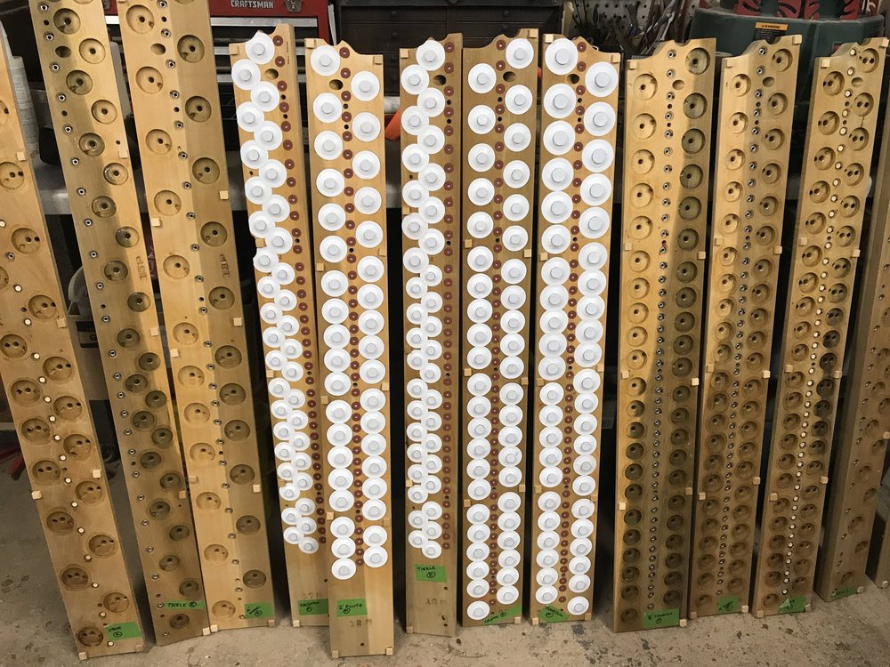
This volume follows a single breath of air from the operator’s hand to the mouth of a speaking pipe. The John Smith Universal is, at heart, an air machine with a paper memory: a hand crank makes wind, a spring-loaded reservoir tames it to a constant pressure, a pressure box distributes it, a punched paper roll decides which notes are called, and a pouch-and-valve action turns each small paper hole into a full-throated pipe. The chain is short and almost entirely pneumatic — there is not a transistor or a magnet in it — but each stage has a specific job, and the interesting engineering lives in the seams between them.
The single most consequential design decision, and the one that separates the Universal (and the 26-note) from the entry-level Basic 20, is valved versus valveless: whether the tracker bar controls the pipes directly or through an amplifying pouch-and-valve stage. That distinction is developed in §5, after the air path is established. Pipe acoustics (scale, cut-up, stopped vs open) are only pointed at here; they are the subject of Vol 05. The pressure box, tracker bar, and valve board are built in detail in Vol 06; the wind system in Vol 04. This volume is the map that ties those subsystems together.
Note: Pressures throughout are stated in inches of water column (in H₂O), the pressure unit used in the John Smith plans and measured on the shop-built manometer (Senger, COAA #24). For reference, 5 in H₂O ≈ 1.24 kPa ≈ 0.18 psi — a gentle pressure, roughly what a healthy set of lungs can hold.
2.1 Block diagram: the air path
The Universal is a serial wind chain with one control input (the paper roll) and one branch point (the stop action, which gates whole ranks). Read left to right: the crank turns a lobed crankshaft; the crankshaft works the feeder bellows, which pump pulses of air; the reservoir stores that air and, via a heavy spring and a spill valve, holds it at a constant working pressure; the pressure box distributes the regulated wind; the paper roll passing over the tracker bar selects notes; and each selected note drives a pouch-and-valve that admits wind to its pipe (Beckman, COAA #31; Senger, COAA #24; Wright, melright.com/busker).
Tip: Everything upstream of the tracker bar exists to deliver steady wind at a known pressure. Everything downstream exists to spend that wind, one note at a time, exactly when the paper says so. Faults sort neatly into those two halves: a wandering pitch or wheezing tone is a wind fault (upstream); a single note that hangs, stutters, or won’t speak is a control fault (downstream).
2.2 Stage 1 — Making wind: crank, crankshaft, and feeders
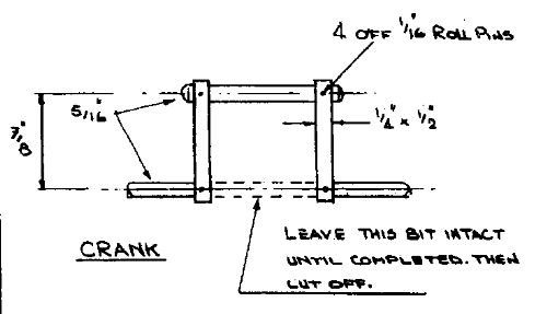
Turning the crank is the only energy input to the instrument; the operator’s arm is the prime mover. The crank drives a crankshaft whose offset lobes convert rotation into the reciprocating motion the feeder bellows need. On the Universal this is a three-lobed crankshaft with the lobes set 120° apart, working three feeder bellows (Beckman, COAA #31). The Basic 20, by contrast, uses a simpler double-bellows arrangement — two feeders on a two-throw crank, working in opposition so that one bellows fills while the other empties (Senger, COAA #24; Wright, melright.com/busker).
The reason for the difference is ripple. Each feeder delivers air only on its compression stroke, so a single feeder produces a strongly pulsating flow. Two feeders 180° apart halve the gaps between pulses; three feeders 120° apart fill them further still, so that at any crank angle at least one feeder is delivering. The result is a smoother raw supply into the reservoir, and therefore a steadier regulated pressure at the pipes — worth the extra complexity on the larger, more wind-hungry valved organ. Feeder geometry, leathering, the connecting rods, and crankshaft fabrication are covered in Vol 04 §“Feeders and crankshaft.”
Table 1 — Stage 1 — Making wind: crank, crankshaft, and feeders
| Wind source | Model | Feeders | Crank throws | Purpose of the choice |
|---|---|---|---|---|
| Double bellows | Basic 20 | 2 | 2 (180°) | Simplicity; adequate for direct-blown pipes |
| Three feeders | Universal / 26 | 3 | 3 (120°) | Smoother wind, higher flow for a valved chest with more ranks |
Source: Beckman, COAA #31 (Universal, three feeders / three-lobed shaft); Senger, COAA #24 (Basic 20, double bellows).
2.3 Stage 2 — Taming wind: reservoir, spring, and spill valve
Feeder output is pulsating and, left alone, its pressure would climb without bound as the operator cranked harder. The reservoir (also called the regulator) solves both problems at once. It is a spring-loaded bellows sitting between the feeders and the pressure box: the feeders pump into it, and it supplies the box (Senger, COAA #24; Wright, melright.com/busker).
Three elements do the regulating:
- The reservoir volume acts as a capacitor. It absorbs the feeder pulses and the momentary gulps taken by sounding pipes, so the pressure the pipes see is far smoother than the flow the feeders deliver. A large chord landing on the roll is met from stored air, not from that instant’s crank stroke.
- A heavy spring (music-wire in the plans; a stout binder clip serves in the “readily-available materials” ethos — Senger, COAA #25) presses the moving reservoir board down onto the stored air. The spring force divided by the board area sets the working pressure, targeted at roughly 5 in H₂O (Senger, COAA #24). A stiffer spring or a smaller board raises pressure; the plans size both to land on ~5 in H₂O and to be checked on the manometer.
- A spill (relief) valve caps the pressure. As the reservoir fills and its board rises, at the top of travel it uncovers or lifts a sprung flap that dumps surplus air to atmosphere (Beckman, COAA #31; Wright, melright.com/busker, “Spill valve”). When the operator over-cranks, the excess simply spills rather than driving the pipes sharp or overblowing them. It is the pneumatic equivalent of a shunt regulator’s dump.
2.3.1 Regulation dynamics
The three elements interact as a first-order pressure regulator. When pipes draw wind, the reservoir board sinks, the spring extends slightly, pressure falls a little, and the drop signals the operator (through crank resistance) to keep cranking; the feeders refill the reservoir and the board rises again. When demand is light and cranking is brisk, the board rises to the spill point and the excess dumps. Working between those limits, the pipes see a pressure that varies only slightly with load and crank speed — the reason a hand-cranked organ can hold a recognizable pitch at all despite an irregular human prime mover.
Because pipe pitch and loudness both depend on wind pressure, the quality of this regulation is directly audible. Slack regulation makes the organ “breathe” sharp on light passages and flat on heavy chords; over-tight spill wastes the operator’s effort. Setting the spring and spill on the manometer, and the pressure-measurement rig itself, are covered in Vol 04 §“Setting the pressure” and Vol 10 §“First wind.”
2.4 Stage 3 — Distributing wind: the pressure box
The regulated wind arrives at the pressure box, the sealed plenum Senger calls “the heart and mechanical backbone” of the instrument (Senger, COAA #24). It is more than a wind chamber: it also carries the roll-transfer mechanism, the tracker bar, the crankshaft supports, the drive to the take-up spool, and the disengage/rewind lever, under a sealed lid (a Lexan window on the Basic 20 so the roll can be watched). The box’s one job in the air path is to present constant, uniform pressure to the underside of every tracker-bar hole simultaneously, so that any note the roll calls is fed from the same wind (Senger, COAA #24; Beckman, COAA #31).
Sealing is therefore not cosmetic. Every unglued seam or porous panel is a leak that lowers box pressure and steals wind from the pipes; the plans stress airtight construction, and Senger notes contact cement proved about twice as strong as silicone for bonding the window (Senger, COAA #25). The box, tracker bar, and their construction are the subject of Vol 06.
2.5 Stage 4 — Selecting notes: the roll and the tracker bar
The paper roll is the program. It travels from the supply spool, across the face of the tracker bar, to the take-up spool, pressed flat against the bar so that it seals the bar’s holes against box pressure. The tracker bar is a row of small holes — one per note — drilled on the roll’s hole spacing (the Universal uses a ~110 mm roll; the Basic 20 uses 31-note Raffin spacing with 20 holes, its holes originally 4 mm, with the lowest three bass notes enlarged to 6 mm for their greater air appetite) (Beckman, COAA #31; Senger, COAA #24; Wright, melright.com/busker, “Tracker bar”). The roll layout, the 20- and 26-note scales, and the full hole map are Vol 03; the drilling jig and honeycomb are Vol 06.
The reading action is pneumatic and binary. While solid paper covers a hole, that hole is sealed and its note is silent. When a perforation in the paper passes over the hole, the hole is momentarily open and box pressure is admitted through it. When the perforation passes on and paper again covers the hole, the note ends. The length of the perforation sets the note’s duration; the roll speed (crank- geared) sets tempo. There is no dynamic information in a hole — only on/off — so expression on a busker organ comes from registration (stops) and arrangement, not from key velocity.
What happens next — whether that admitted puff of air is the note or merely triggers it — is exactly the valved/valveless divide.
2.6 Stage 5 — Sounding the note: valveless vs valved
2.6.1 The valveless action (Basic 20)
In the Basic 20 the tracker bar hole is piped directly to a pipe. There is no intermediate valve: “the paper roll and the tracker bar are the valves” (Senger, COAA #24; johnsmithbusker.co.uk). When a perforation opens a tracker hole, box pressure flows straight down the tube and blows that pipe; when the paper re-covers the hole, the pipe stops. It is beautifully direct, and its directness is the whole appeal — no leather pouches to make, no bleeds to adjust, a build within reach of an average handyman (johnsmithbusker.co.uk).
The directness also sets the limits. Every bit of wind a pipe consumes must pass through its small paper/tracker hole, so the hole size caps the pipe size: this is precisely why the Basic 20’s three bass notes need enlarged 6 mm holes to feed their thirstier pipes (Wright, melright.com/busker). It also means the paper edge does the sealing directly against full pipe-wind demand, so roll tracking, paper grip, and hole registration are critical, and adding more or larger pipes (more ranks) is impractical — there is no wind headroom and no way to gate ranks.
2.6.2 The valved action (Universal / 26-note)
The Universal interposes a pouch-and-valve stage between each tracker hole and its pipe (Beckman, COAA #31). Now the air admitted through the paper hole is only a control signal: it does not blow the pipe, it operates a valve that does. The valve draws its pipe wind straight from the pressure box through a generous passage, so the pipe is no longer starved by the tiny paper hole. This is a pneumatic amplifier — a small, low-flow signal controlling a large, high-flow supply — and it is what lets the Universal carry four melody ranks plus bass and a glockenspiel where the Basic 20 carries one direct-blown rank.
The Universal’s valve is a 1/4 in poplar dowel faced with a leather punching, on a 1/8 in brass stem, seated in a valve box above a pillow-pouch board; the pouches are of zephyr skin or thin leather, and the action carries adjustable bleeds (Beckman, COAA #31). The sequence for one note:
- Rest. Paper covers the tracker hole. The pouch well below the pouch is not pressurized; the pouch lies flat, the valve sits closed on its seat, and no wind reaches the pipe.
- Trigger. A perforation opens the tracker hole. Box pressure passes through the paper hole and the tracker tube into the pouch well, inflating the pillow pouch.
- Speak. The swelling pouch pushes up on the valve stem, lifting the leather- faced valve off its seat. Wind from the pressure box now flows past the open valve, up the pipe’s supply tube, and the pipe speaks (Beckman, COAA #31; general pouch-action principle, Wright, melright.com/busker).
- Release. The perforation passes; paper re-covers the tracker hole. The trapped air in the pouch well now escapes through a small bleed to atmosphere (or the box’s low side); the pouch deflates, the valve reseats under its own weight and wind pressure, and the note stops.
2.6.3 The bleed, and why it is adjustable
The bleed is a small, deliberate leak from the pouch well. It is the detail that makes the valved action work as a repeating switch rather than a one-shot, and it embodies a genuine trade-off:
- Too large a bleed and the well can never build enough pressure to fully inflate the pouch — the valve lifts weakly or not at all, and the note is soft, slow to speak, or silent. The leak steals the very signal air it is meant to vent.
- Too small a bleed and the well cannot dump fast enough when the paper re- covers the hole — the pouch stays inflated, the valve hangs open, and the note drags or ciphers after the perforation has passed.
The bleed must therefore be small enough to let the well pressurize decisively on a puff of signal air, yet large enough to collapse the pouch cleanly the instant the paper closes the hole. Because the ideal size depends on pouch stiffness, valve weight, well volume, and pipe demand, the John Smith valve is built with adjustable bleeds so the release can be tuned per note on the bench (Beckman, COAA #31). Setting bleeds and chasing hung notes is a voicing task in Vol 06 §“Pouch-and-valve action” and Vol 10.
2.6.4 Why valves unlock ranks and stops
Because a valved note is driven by box wind rather than by wind squeezed through the paper, the design gains headroom that the valveless organ simply does not have. That headroom is what makes the Universal’s four melody ranks — a set of open flutes, a set of stopped (closed) flutes, an open rank an octave higher, and a front rank tuned slightly sharp to beat against another for tremolo — plus five bass pipes with octave “helpers” and an optional glockenspiel all playable from one 20/26-note roll (Beckman, COAA #31; pipe details in Vol 05).
It also makes stops (registers) possible. A stop gates the wind supply to a whole rank at the chest, upstream of that rank’s valves: with the stop off, the rank’s valves may open on every note but no wind reaches its pipes, so the rank is silent; with the stop on, the rank sounds along with any others selected. This is the branch shown returning into the valve chest in the block diagram — one control that enables or mutes a rank en masse, independent of what the roll is calling note by note. A valveless organ has no such layer: its single rank is always “on” whenever a hole opens, so registration is not available at all. The stop mechanism itself — sliders/valves and their linkages — is built in Vol 06.
Warn: The pouch-and-valve stage is the Universal’s reward and its tax. It is what lifts the instrument from a one-rank novelty to a real four-stop organ, but every note now has a pouch to leather, a valve to seat, and a bleed to set. The Basic 20 trades that capability away for a build a beginner can finish. Vol 01 §“Why the Universal” weighs that choice for a first build.
2.7 Putting the chain back together
A single sounded note, traced end to end, is: the operator cranks; the three feeders pump pulses; the reservoir’s spring holds those pulses at ~5 in H₂O and its spill dumps any excess; the pressure box presents that wind uniformly beneath the tracker bar; a perforation in the roll opens one tracker hole and admits a puff of that wind; on the Universal that puff inflates a pouch that lifts a valve, and the valve lets box wind up the pipe so it speaks; and when the perforation passes, the bleed collapses the pouch, the valve reseats, and the note ends — unless its rank’s stop was off, in which case the whole chain ran silently for that rank. On the Basic 20 the middle steps vanish: the puff of wind is the note.
Every later volume attaches to one link of this chain. The wind system (feeders, crankshaft, reservoir, spring, spill, manometer) is Vol 04. The pipes and the four ranks are Vol 05. The pressure box, tracker bar, and the pouch-and-valve chest — including the valveless contrast in hardware terms — are Vol 06. The drive that moves the roll across the tracker bar at the right speed is Vol 07. The scales and the roll layout that decide which holes exist are Vol 03. This volume is only the map; the territory is those chapters.
Sources
- Beckman, “John Smith Universal (20/26) Organ,” Carousel Organ #31 (COAA) — the Universal as a valved organ; three feeder bellows on a three-lobed crankshaft (lobes 120° apart); reservoir with sprung spill/relief valve; valve = 1/4 in poplar dowel + leather punching on a 1/8 in brass stem over a pillow-pouch board (zephyr skin/leather), with adjustable bleeds; four melody ranks + five bass pipes + bass helpers + optional glockenspiel; ~110 mm roll.
- Senger, “Building the John Smith Organ,” Carousel Organ #24–25 (COAA) — operating pressure 5 in H₂O with a shop-built manometer; Basic 20 double bellows + single reservoir with heavy spring and relief valve; the pressure box as “the heart / mechanical backbone”; tracker holes 4 mm with the lowest three bass at 6 mm; 31-note Raffin spacing, 20 holes; contact-cement-vs-silicone sealing note; readily-available-materials substitutions (binder-clip spring).
- Wright, melright.com/busker (Melvyn Wright’s John Smith pages) — valveless operation (paper roll + tracker bar are the valves; pipes blown directly; enlarged bass holes for greater air consumption); the crank → connecting rods → alternating bellows description; the reservoir “Spill valve” page.
- johnsmithbusker.co.uk (John Smith / Roll Cutter) — the Universal plays both the Raffin 20-note and Alderman 26-note scales; the valveless design’s simplicity as the reason for the range’s success.
- General organ pouch/valve/bleed action (pressure-pneumatic principle: a perforation admits wind to a pouch well, the pouch lifts a valve/pallet, a bleed equalizes the well after the perforation passes) corroborated against johnwolff.id.au (14-note organette) and standard windchest-action references.
Cross-references: the wind system (feeders, three-lobed crankshaft, reservoir, spring, spill valve, manometer, setting ~5 in H₂O) in Vol 04; the four flute ranks, bass pipes/helpers, and glockenspiel in Vol 05; the pressure box, tracker bar (4 mm/6 mm holes, honeycomb, drilling jig), and the pouch-and-valve chest with the valveless hardware contrast in Vol 06; the roll drive and transport across the tracker bar in Vol 07; the 20- and 26-note scales and the tracker-bar hole map in Vol 03; the valved-vs-valveless choice weighed for a first build in Vol 01.
Comments (0)