John Smith Universal Organ · Volume 7
The John Smith Universal — Vol 07: Drivetrain & Roll Transport
This volume follows the mechanical power after it leaves the operator’s hand and before it becomes music. Vol 04 §3.2 developed the three-lobed crankshaft (lobes 120° apart, a 5/16 in / 7.9 mm steel rod) as a wind engine — how its throws drive the three feeder bellows that charge the reservoir. That same crankshaft has a second, quieter job: it advances the paper roll past the tracker bar. This volume owns that second job end to end — the friction drivetrain (friction wheel → spring-loaded idler → take-up-spool drive wheel), the roll path (supply spool → tracker bar → take-up spool), the rewind/disengage arrangement, the spool holder, and the cranking ergonomics that couple crank cadence to both pitch (via wind pressure) and tempo (via roll advance). The pressure box that houses this gear is Vol 06’s subject; the roll itself, its 110 mm width, and the 20-/26-note scales it carries are Vol 03’s. Motorised or MIDI automation of the transport is out of scope here and belongs to the program’s automation/MIDI dive (Dive 12).
Voice/units note. Rod and wheel dimensions are given in inches (with metric), rotational rates in rpm / rev·s⁻¹, and roll speeds in mm·s⁻¹. Values from the two COAA build articles are cited (Senger, COAA #24–25) and (Beckman, COAA #31); community build detail is cited by name — Melvyn Wright’s John Smith pages (melright.com/busker), and the organcrank.blogspot.com build log. Figures the sources do not pin down are marked (est.) and never invented.
7.1 One crank, two loads
The defining economy of the John Smith design is that a single hand crank does two jobs at once: “A crank handle is turned which operates a crankshaft that moves the paper music roll from one spool to another and operates two bellows which pressurise an air reservoir” (johnsmithbusker.co.uk). On the Universal the bellows count rises to three (Vol 04), but the principle is unchanged — the crankshaft is a shared prime mover feeding two mechanically independent loads:
Table 1 — mover feeding two mechanically independent loads
| Load | Path from crankshaft | Governed quantity | Developed in |
|---|---|---|---|
| Wind | Lobes → connecting rods → feeders → reservoir | Wind pressure (~5 in H₂O) | Vol 04 |
| Roll advance | Friction wheel → idler → take-up-spool wheel | Roll speed / musical tempo | This volume |
The two loads are coupled only through the operator’s arm: crank faster and the feeders pump harder (pressure firms up, pitch and volume rise a touch) and the roll advances faster (tempo rises). This shared dependence is the central ergonomic fact of the instrument and is treated in §6. John Smith’s standing advice to first builders was to leave the working parts strictly alone — “bellows; reservoir; spill valve; spring; idler wheel; clutch; tracker bar; and pipe construction” (johnsmithbusker.co.uk, History). The idler and its clutch — the subject of this volume — are on that do-not-modify list precisely because the transport is delicate.
7.2 The friction drivetrain
7.2.1 Why friction and not gears
The transport is a friction drive, not a positive gear or chain drive — a deliberate choice. A slipping friction coupling tolerates the roll fouling, a jammed spool, or a hand on the paper during loading without shearing anything (the idler simply slips), and it lets the take-up spool absorb the changing pull of an accumulating roll (§3.3) without a tensioner. The cost is that a friction train can skip if any contact surface is glazed, greasy, or uneven — hence the tire preparation in §2.3.
7.2.2 The friction wheel on the crankshaft
Power is tapped off the crankshaft by a small friction (drive) wheel fixed to the 5/16 in (7.9 mm) crankshaft rod. In the readily-available-materials idiom it is built up two ways: a cardboard-wound disc (strips of card wound and glued onto the shaft, then trued, with an abrasive rim), or a turned hardwood dowel faced with abrasive. Builders commonly glue a strip of belt-sander cloth (aluminium-oxide) around the rim as the drive surface, joining the ends with a shallow 45° lap joint rather than a butt joint so the splice passes the idler smoothly and does not produce a once-per- revolution “tick” or a spot of lost grip (Melvyn Wright, John Smith pages; John Smith plans). The 45° lap separates a wheel that drives evenly from one that pulses.
One documented builder substituted the wood-and-abrasive wheel with a knurled steel collar — a microphone-stand base adapter that measured 18 mm in diameter — relying on the knurling for grip (organcrank.blogspot.com). That is a legitimate alternative to the abrasive rim, and it fixes the wheel diameter usefully for the ratio estimate in §4.
7.2.3 The idler wheel and its tire
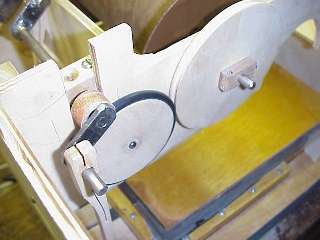
Between the crankshaft’s friction wheel and the take-up-spool wheel sits the idler wheel, a wooden wheel roughly 2.5 in (63 mm) in diameter carried on a spring-tensioned axle (organcrank.blogspot.com). Its rim is grooved to seat a tire, and the canonical tire is a vacuum-cleaner drive belt — a Hoover-type rubber belt — pressed into a groove cut in the wheel edge (Senger, COAA #24–25; organcrank.blogspot.com). The groove is cut with a round or bullet-shaped grinding point (e.g. a Dremel stone), which gives fast stock removal and good control of the seat profile (organcrank.blogspot.com).
Warn — file the lettering off. Vacuum-cleaner belts are moulded with raised part-number lettering on the belt surface. Left in place, that raised text makes the idler ride high once per belt circumference and the drive skips in time with the lettering. The belt must be dressed — the raised lettering filed or sanded flush — before it will drive smoothly (John Smith plans; Melvyn Wright, John Smith pages). This is the single most common cause of a transport that advances the roll unevenly.
The idler is the “clutch” element John Smith lists as do-not-modify: a light spring holds it in simultaneous contact with the crankshaft’s friction wheel on one side and the take-up-spool wheel on the other, so it both transmits drive and, by slipping, protects the train.
7.2.4 The take-up-spool drive wheel
The third wheel is the largest — a wooden spool wheel roughly 3.75 in (95 mm) in diameter fixed on the same axle as the take-up spool, so the spool turns with it (organcrank.blogspot.com). Like the idler it is grooved and could carry a belt, but in the running train the idler’s tire bears directly on this wheel’s rim: “The larger of the wheels is on the same axle as the take-up spool and it is driven by the rotating action of the crankshaft which is translated through a spring-tensioned axle that holds the idler wheel … the idler wheel is fitted with a rubber ring and it uses the rubber friction and the spring tension to keep it in contact with the spool wheel” (organcrank.blogspot.com).
Bearings throughout the train follow the Universal’s low-friction practice — bronze bushings and UHMW blocks (Beckman, COAA #31) — because any drag here shows up as a crank that is heavier on the roll side and, worse, as a train more prone to slip.
7.2.5 The disengage lever
A lever lifts the spring-loaded idler out of contact, breaking the drive between the crankshaft’s friction wheel and the take-up-spool wheel. Disengaging serves three routine needs:
- Loading a fresh roll — the take-up spool must turn freely to take up slack and the roll must feed without the transport fighting it.
- Rewinding — the played roll is wound back onto the supply spool by hand (§3.2) with the take-up spool free.
- Static wind test — the operator can crank purely to raise wind (feeders and reservoir, Vol 04) with the roll stationary, for leak-chasing, voicing, and tuning, without paper marching past the tracker bar (Senger, COAA #24–25).
The lever is the reason the wind system and the transport can be exercised independently even though they share one crank.
7.3 The roll path and the spools
7.3.1 Supply spool, tracker bar, take-up spool
The paper roll runs the classic three-station path of every book-and-roll organ: it pays off a supply spool, passes over the tracker bar (where its punched holes are read pneumatically — Vol 06), and is wound onto the take-up spool that the drivetrain turns. The Universal uses ~110 mm roll stock and reads it against 31-note Raffin roll spacing even though only 20 (or 26) tracks are punched (Vol 03; Senger, COAA #24–25). Off-the-shelf 31-note Raffin supply spools therefore drop straight in as the feed spool, which is one reason the design settled on that spacing.
7.3.2 The take-up spool and the 5 mm hex rewind
The take-up spool is another readily-available-materials item: a length of rain-water downspout or a cardboard mailing tube serves as the core the played paper winds onto (Senger, COAA #25; the anchors’ materials list). Because the take-up spool shares its axle with the 3.75 in spool wheel (§2.4), the transport turns it directly.
Rewinding runs the process backwards. The idler is disengaged (§2.5) so the take-up spool is free, and the supply spool is turned by hand to reel the paper back. The Raffin supply spool carries a hexagonal socket in its end that fits a 5 mm hex (Allen) key perfectly, so rewinding is done by fitting a 5 mm hex key or crank to that socket and winding (organcrank.blogspot.com; Senger, COAA #24–25). The 20-Note Senior and 26-Note variants offer a built-in rewind mechanism (an “automated conductor”) that formalises this; the Basic 20 and many Universal builds rewind by hand off the 5 mm hex (anchors; Senger, COAA #24–25).
7.3.3 Take-up geometry: tempo drift through the roll
A subtlety of any take-up-spool drive is that the driven surface is the paper already wound on the spool, whose effective diameter grows as the roll transfers. With the spool wheel at a fixed angular rate ω, the paper’s linear speed is v = ω·(d_eff/2), and d_eff climbs from the bare core toward the full-roll diameter as play proceeds. The roll therefore tends to speed up (tempo rises) across a long roll — a known trait of spool-driven transports, not a fault. The slipping idler does not force a rigid ratio, and arrangers (Vol 03) lay out music with the characteristic in mind. A worked estimate follows in §4.
7.4 Ratios, cadence, and roll speed (estimate)
No consulted source states the drivetrain’s numeric reduction or the roll’s linear speed, so the following is a worked estimate (est.) from the published wheel diameters, offered to fix the scale rather than as a spec.
Taking the friction wheel at the documented 18 mm knurled-collar case (organcrank.blogspot.com), the idler at 2.5 in (63 mm) and the take-up-spool wheel at 3.75 in (95 mm), and noting that an idler transmits motion without changing the overall ratio (its size sets contact and packaging, not reduction), the crankshaft-to- take-up-spool ratio is set by the friction wheel against the spool wheel:
reduction ≈ spool-wheel dia / friction-wheel dia
          ≈ 95 mm / 18 mm ≈ 5.3 : 1   (take-up spool turns ~5× slower than the crank)
Table 2 — 4. Ratios, cadence, and roll speed (estimate)
| Quantity | Estimate | Basis |
|---|---|---|
| Crank cadence (comfortable busking) | ~55–65 rpm (≈1 rev·s⁻¹) | typical hand-organ practice (est.) |
| Friction wheel dia | 18 mm | organcrank.blogspot.com (knurled collar) |
| Take-up-spool wheel dia | 95 mm (3.75 in) | organcrank.blogspot.com |
| Take-up spool speed | ~0.19 rev·s⁻¹ | 1 rev·s⁻¹ ÷ 5.3 (est.) |
| Bare take-up core dia | ~40 mm (downspout/tube) | anchors’ materials list (est.) |
| Roll speed, roll just started | v = π·40·0.19 ≈ 24 mm·s⁻¹ | geometry (est.) |
| Roll speed, roll well built up (d_eff ≈ 75 mm) | v ≈ π·75·0.19 ≈ 45 mm·s⁻¹ | geometry (est.) |
The spread — roughly 24→45 mm·s⁻¹ across a roll — is the tempo-drift of §3.3 made concrete: at a fixed crank cadence the same roll plays perhaps half again as fast near its end as at its start (est.). In practice the operator trims cadence to hold tempo by ear, which is exactly the ergonomic coupling §6 describes.
7.5 The spool holder and paper alignment
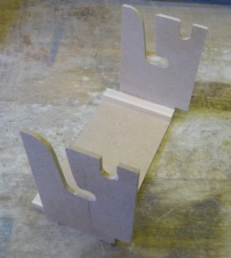
The spool holder is the frame in the pressure box (Vol 06) that carries both spools on their axles and sets their spacing and their alignment to the tracker bar. Two alignment problems dominate:
- Lateral tracking. The paper’s punched tracks must line up with the tracker-bar holes across the whole roll, or notes mis-read and the edge frets. Alignment is set with side spacers / washers on the spool axles that fix each spool’s lateral position (Senger, COAA #24–25).
- Rim drag. If a spool’s flanges or the holder’s cheeks bear on the edges of the paper, the roll is braked unevenly and can tear. The spacers are sized so the roll runs with a whisker of clearance and the rims do not rub the paper (Senger, COAA #24–25). Getting this clearance right — enough to free the paper, little enough to keep tracking — is the fussy part of setting up a fresh roll.
A light back-tension on the supply side keeps the paper flat against the tracker bar so holes seal cleanly over the bar’s ports; John Smith’s economy build even improvises the lid paper tensioner from coat-hanger wire (anchors’ materials list).
7.6 Cranking ergonomics
7.6.1 Cadence sets pitch and tempo together
Because the crankshaft feeds both the feeders and the roll, crank cadence is a single control with two outputs. Turn faster and (a) the feeders pump harder, so reservoir pressure firms toward and past its set point — Vol 04’s spill valve dumps the surplus, so pitch and volume move only a little — and (b) the take-up spool turns faster, so the roll advances faster and the music speeds up. The wind side is regulated (the sprung reservoir and spill valve hold pressure over a working band of cranking speeds, Vol 04 §6), but the roll side is not — roll advance is directly proportional to crank speed. The practical consequence: tempo is far more sensitive to cadence than pitch is. A player who speeds up to be heard over a crowd will run the music fast well before the organ goes noticeably sharp.
Tip. The goal is a steady cadence, held by the feel of the crank and the ear on the tempo, not a fast one. A metronomic ~1 rev·s⁻¹ that never wavers gives constant tempo and, incidentally, the smoothest wind. Lurching the crank shows up first as tempo wobble and only second as pitch waver.
7.6.2 The handle
The crank handle is a 1/2 in (12.7 mm) aluminium bar in the standard build (Beckman, COAA #31; anchors). The known failure mode is a handle with a bent arm — an L-shaped or cranked aluminium arm — which fatigues and cracks at the bend after enough revolutions, because aluminium work-hardens and is a poor fatigue performer at a stress-concentrating corner. The community fix is to make the arm from flat brass bar instead, which tolerates the repeated bending stress far better, or to avoid the sharp bend geometry altogether (Melvyn Wright, John Smith pages). An organ is cranked tens of thousands of revolutions per busking session, so the handle is a genuine fatigue part, not a trivial one.
7.6.3 The centre-connecting-rod interference (the “U-bend” fix)
A specific build gotcha lives where the two subsystems share the crankshaft. On the three-feeder Universal, the centre feeder’s connecting rod (Vol 04 §7.1) and the idler-wheel axle can occupy the same swept volume — the connecting rod, swinging with the crank, fouls the idler’s axle. The documented fix is to put a shallow “U” bend in the connecting rod so it steps around the idler axle and clears it through the full crank rotation (John Smith plans; Melvyn Wright, John Smith pages). It is worth checking for during trial assembly (Vol 09): rotate the crank slowly by hand through a full turn and watch the centre rod pass the idler axle before committing any glue or pins.
Warn. This interference is easy to miss on the bench with the transport disengaged and the rod at rest. It only shows when the crank is turned through a full revolution with everything mounted. Clear it with the U-bend before final assembly, not after.
7.7 Summary and cross-references
The Universal’s transport is a study in doing the most with the least: a shared crankshaft, three plain wooden wheels, a vacuum-cleaner belt for a tire, a downspout for a spool, a 5 mm hex key for a rewind, and a single lever to throw the whole thing out of gear. Its behaviours all follow from the friction-drive-plus-take-up-spool architecture — the deliberate slip that protects the paper, the tempo drift as the take-up roll builds, and the tight coupling of crank cadence to tempo through a shared prime mover.
- Wind side of the shared crankshaft (lobes, connecting rods, feeders, reservoir, spill valve): Vol 04.
- The pressure box that houses this drivetrain and the spool holder, and the tracker bar the paper is read against: Vol 06.
- The roll itself — 110 mm stock, 31-note Raffin spacing, the 20-/26-note scales, arranging around the tempo-drift characteristic: Vol 03.
- Trial assembly and interference checks (the U-bend, tracking): Vol 09.
- Motorised / MIDI automation of the transport: the program’s automation/MIDI dive (Dive 12).
Sources
- Beckman, COAA #31 — John Smith Universal (20/26) Organ — three-lobed crankshaft (5/16 in steel), friction/idler/take-up drive, vacuum-cleaner belt tire, bronze/UHMW bearings, 1/2 in aluminium crank.
- Senger, COAA #24–25 — Building the John Smith Organ — pressure box housing the roll-transfer mechanism, drive wheels, disengage lever for rewind/loading/test; readily-available-materials list (downspout/mailing-tube take-up spool, vacuum-cleaner belt idler tire, coat-hanger tensioner); alignment spacers.
- Melvyn Wright, John Smith pages (melright.com/busker, incl. building-tips article jsart36) — belt-lettering-must-be-filed, 45° lap joint on the abrasive rim, flat-brass handle-arm fix, centre-rod “U”-bend interference fix.
- organcrank.blogspot.com (homemade-crank-organ build log) — idler 2.5 in / spool wheel 3.75 in wooden wheels, spring-tensioned idler axle, Hoover-belt tire in a ground groove, 18 mm knurled-collar friction-wheel substitute, 5 mm hex socket on the Raffin supply spool for rewind.
- johnsmithbusker.co.uk (and /beginning.html, History) — “one crank moves the roll and pumps the bellows”; John Smith’s do-not-modify list (bellows, reservoir, spill valve, spring, idler, clutch, tracker bar, pipes).
- _SOURCE_ANCHORS.md (this deep dive) — consolidated build facts and materials list.
Cross-references: the shared crankshaft, feeders, reservoir and spill valve in Vol 04; the pressure box, spool holder and tracker bar in Vol 06; the roll, scales and arranging in Vol 03; trial fit and interference fixes in Vol 09; automation/MIDI drive in the program’s Dive 12.
Comments (0)