John Smith Universal Organ · Volume 9
John Smith Universal — Vol 09: Assembly Sequence
Vol 08 delivered roughly 800–900 prepared parts — pipe blanks, chest laminations, bellows boards, a drilled tracker bar, turned wheels, leather cut to grade. This volume glues them up in the right order. The order is not a preference; it is dictated by two hard dependencies. First, several subassemblies bury others: once the pipes stand on the pipe board there is no reaching the valve chest beneath them, and once the case is closed there is no reaching the pressure box inside it. Second, airtightness must be proved before it is sealed in — a leak found with a manometer on an open bench is a five-minute fix; the same leak found after the pipes are mounted and the case is glued is a teardown. The build order that Paul Senger’s roughly one-year log follows, and that this volume formalises, is the order that keeps every joint reachable until it has been proved (Senger, COAA #24/#25).
The high-level sequence is pipes first, then the tracker bar, then the bellows and reservoir, then the pressure box, then mount the pipe board and pipes, then build the case around the mounted assemblies, then tube everything up, and finish with voicing and tuning (handed to Vol 10). Each stage is validated before the next begins. The through-line under all of it is sealing: on a pressure-wind organ a leak is not cosmetic — it is a weak, late, or silent note.
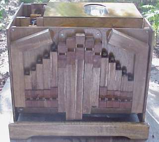
9.1 The dependency logic
A crank organ is easy to build in the wrong order and very hard to finish in the wrong order. Three rules govern the sequence:
- Build the slow, repetitive, error-tolerant work first. The pipes are ~300 of the ~800 parts (Senger, COAA #25) and take the longest — roughly five weeks in Senger’s log — but a mis-cut pipe is a cheap spare, not a stalled build. Doing them first turns dead time (glue curing on 90-odd pipe bodies) into progress and lets the builder’s hands learn the craft on the most forgiving parts before the precision work.
- Build every airtight or precision-critical subassembly so it can be tested in isolation, and test it before it is enclosed. The tracker bar, each bellows, the reservoir, the pressure box, and the pouch/valve chest each get a bench test before they are joined to anything that would hide a fault.
- Assemble outward from the core, and close the case last. The pressure box is the mechanical backbone (Vol 06); the pipe board mounts on it; the case wraps around the mounted assemblies. The case is the last structural step, not the first, because its final internal dimensions are only known once the pipes and box are actually fitted (Senger, COAA #24; Beckman, COAA #31).
9.2 The subassembly build order
The table below is the working order, with the dependency that fixes each item’s place and the bench test that must pass before the next stage. Durations are from Senger’s log and are order-of-magnitude for a first build (est.).
Table 1 — The subassembly build order
| # | Subassembly | Why here in the order | Bench test before proceeding | Detail in |
|---|---|---|---|---|
| 1 | Pipes (4 ranks + 5 bass + 5 helpers) | Longest, most repetitive, most error-tolerant; ~5 weeks; a bad pipe is a cheap spare | Each body glued square in the jig; blow across the mouth — it speaks; no seam leaks | Vol 05 |
| 2 | Tracker bar + honeycomb | Accuracy-critical; must be right before anything depends on its register; can proceed alongside the pipes | Lay a punched roll over it; every hole registers on a track centre | Vol 06, Vol 08 |
| 3 | Feeder bellows + reservoir | The wind source everything downstream is tested against; needed to pressure-test the box | Each feeder holds; reservoir holds and the spill valve caps pressure at ~5 in H₂O | Vol 04 |
| 4 | Pressure box + valve chest + pouches | The mechanical backbone; the pipe board mounts on it; must be sealed and proven while still open | Seal the tracker holes, wind the box, watch the manometer for droop; every pouch well inflates and holds | Vol 06 |
| 5 | Mount pipe board + pipes | Buries the chest — must be reachable-by-design (removable mounts) before this step | Every pipe seats and lifts off its mount without tools breaking anything | this volume |
| 6 | Case around the mounted assemblies | Final internal size is only known once box + pipes are fitted; closing it hides the interior | Trial-fit dry; nothing fouls; lid gasket seals; then rip to final width | this volume |
| 7 | Tube everything up | Last connection step, done with subassemblies in place so run lengths are real | Wind the whole organ; no kinks, no cross-talk, no dead note traceable to a tube | this volume |
| 8 | Voice + tune | Needs the finished, wound instrument | Handed to Vol 10 | Vol 10 |
9.3 Airtightness: the through-line
Every stage above carries a leak test, and they are all the same test in different clothes: pressurise the subassembly, seal its ports, and watch a manometer for droop. On a ~5 in H₂O (127 mm H₂O ≈ 1.24 kPa) organ the panels are barely stressed, but the box is porous by a thousand small paths — a bearing where a shaft passes a wall, a lever slot in the lid, a screwed-down spool bracket, a fuzzy router channel, a pouch glued down proud on one edge (Senger, COAA #24/#25; Vol 06). Each path lowers the pressure the pipes see, and a pipe run slightly low on wind speaks flat, late, and thin — a fault that looks like bad voicing but is really a leak two subassemblies upstream.
The discipline is to prove each vessel before it is enclosed and never to chase, at the pipe, a leak that could have been found on the bench. The sealing kit is the one from Vol 08 used to its purpose: fish glue on every leather joint (gussets, pouches, valve faces — never PVA, which dries stiff and cracks a flexing gusset), contact cement, not silicone, on the Lexan lid window (roughly twice the bond strength for a joint that must hold box pressure, and it does not creep), adhesive weather-strip or split-leather gaskets under every removable lid and access panel, and glued, sanded-flat wood-to-wood seams everywhere else (Senger, COAA #25).
9.4 The phased build
9.4.1 Phase 0 — plan, prototype the hard fits
Before any structural glue, the two or three genuinely awkward geometric fits are worked out in cardboard mock-ups. Senger builds cereal-box cardboard prototypes of the tricky parts — the way the mitred bass pipes fold under the skirt, how the pipe board sits over the box, where the tracker take-offs land — because cardboard is free and a cut-and-tape mistake costs nothing, whereas the same mistake in Baltic birch costs a sheet and a week (Senger, COAA #24/#25). The pipe scale (Vol 05) and the cut plan (Vol 08) are finalised here so the pipe blanks are cut with the +5–10 % length margin (and +1 in on the largest three basses for mitring) intact.
9.4.2 Phase 1 — the pipes (roughly five weeks)
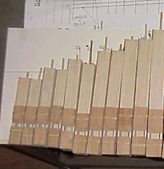
The pipes come first because they are the longest, most repetitive, and most forgiving work — turning glue-cure dead time into progress while the hands learn the craft. Each melody rank of ~20–26 pipes is glued up in the right-angle gluing jig (Vol 08) so no body racks, and each pipe is proved as it comes off the jig: blow across the mouth — it should speak; check every seam for a leak. The five bass pipes are cut long and mitred into U or P folds so they fold under the skirt (see interference below), and the five bass helpers (tuned an octave up) are built small to sit on top of the bellows (Vol 05). Fine voicing is deferred to Vol 10 — here the pipes only have to be sound, square, and airtight.
9.4.3 Phase 2 — the tracker bar
The tracker bar is drilled (or the ready-made Roll Cutter bar is fitted) by the cumulative-dimension method against a drill-press fence, and its honeycomb fanned out behind it (Vol 06). It is validated by laying a punched roll over the finished bar and confirming every hole registers on a track centre; there is no downstream fix for a mis-drilled bar. This runs in parallel with the pipes — neither depends on the other — but it must be finished and proven before the pressure box that carries it is closed.
9.4.4 Phase 3 — the bellows and reservoir
The three feeder bellows and the reservoir are leathered and assembled next, because they are the wind source every later subassembly is tested against. Gussets are fish-glued (never PVA); flap valves are cut from valve-heavy leather; the reservoir spring is set and the spill/relief valve adjusted so the reservoir caps at about 5 in H₂O (Vol 04). Each feeder is leak-tested on the bench, then the assembled wind unit is proved: it must hold pressure with the crank still and the spill valve must open cleanly at the limit rather than letting the pressure climb.
9.4.5 Phase 4 — the pressure box and valve chest
The pressure box is glued up as a sealed plenum, the tracker bar mounted across its top face, the laminated valve chest router-cut and skinned, and the pouch board leathered (Vol 06). This is the most complex subassembly and the one most punishing to get wrong, because everything above it will hide it. It is proved in two tests: seal the tracker holes, wind the box from the reservoir with the drive disengaged, and watch the manometer for droop; then wind the chest and confirm every pouch well inflates and holds and no valve hangs. A well that leaks or a valve that sticks is fixed now, with the box open, not after the pipes are on top.
Warn: The valve chest gets buried under the pipe board and pipes. Build it so it can still be reached — a removable valve box and an accessible pouch board — and prove every well before mounting anything above it. A hung valve discovered after the pipes are mounted means pulling the pipes to reach it (Vol 06).
9.4.6 Phase 5 — mount the pipe board and the pipes
The pipe board is mounted on the pressure box, and the pipes go on. The single governing principle is removability: because the chest below must remain serviceable, pipes are mounted so any one can come off without disturbing its neighbours or breaking anything.
- Melody pipes — T-nuts and 6-32 machine screws. The preferred mount presses a T-nut into the pipe foot (or board) and holds the pipe with a 6-32 machine screw, so a pipe unscrews cleanly for voicing or chest access. Small wood screws are the cheaper alternative but strip after a few removals — the T-nut is the removable-by-design choice (Senger, COAA #25; builder practice, Wright).
- The middle five — upside-down hooks. Five of the middle pipes, awkwardly placed, are hung on inverted hooks so they lift off upward rather than unscrewing from a face there is no room to reach (Wright, melright.com/busker).
- The large front pipes — cross-pieces. The big front pipes are held by wooden cross-pieces (retaining bars) rather than individual foot screws, spreading their weight and letting the whole group be freed by removing a bar.
9.4.7 Phase 6 — build the case around the mounted assemblies
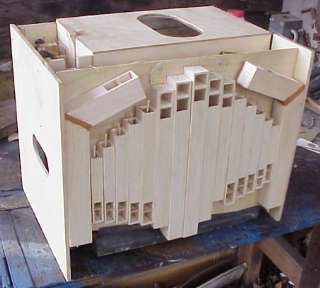
Only now, with the box and pipes fitted, are their true assembled dimensions known — so the case is built around them rather than to a drawing. The case is trial-fitted dry: the sides are offered up, everything is checked to clear (pipes, mitred basses, crank, lever slots), and only when nothing fouls is the case ripped to its final width on the table saw. Building oversize and ripping to fit after trial assembly is the standard trick — it absorbs the accumulated tolerance of 800 parts instead of demanding they all land on nominal (Senger, COAA #24). Lid and access-panel gaskets (weather-strip or split leather) are fitted so every removable panel still seals.
9.4.8 Phase 7 — tube everything up
With the subassemblies in their final positions, the actual tube runs are known, so tubing is done last: honeycomb take-off → pouch board → valve → pipe supply, brass nipple to neoprene tube (or glued-in vinyl on the economy build) (Vol 06). Runs are kept short, snag-free, and unkinked — a pinched signal tube softens or delays exactly one note. The whole organ is then wound and every note walked through: any dead, weak, late, or ciphering note is chased here, with a tube or a bleed, before voicing begins.
9.4.9 Phase 8 — first wind, voicing, tuning → Vol 10
The instrument is now complete and airtight. First wind, systematic leak chasing, voicing the flue pipes (cut-up, cover position, ears on the basses), and tuning to a temperament with the manometer-and-microphone rig are the subject of Vol 10.
9.5 Common interference problems and their fixes
Every one of these is documented in the John Smith community and every one is found during trial-fit — which is why Phase 0 prototyping and Phase 6 dry assembly exist. Catching them on cardboard or in a dry fit is a fix; catching them after glue-up is a rebuild.
Table 2 — Common interference problems and their fixes
| Problem | Where it bites | Fix | Source / detail |
|---|---|---|---|
| Bass pipes too long to stand in the case | Phase 1 / Phase 6 | Mitre the basses into U or P folds to run horizontally under the skirt; add ears at the mouth to lower pitch ~½ note without more length; if still tight, add case depth | Vol 05; Senger, COAA #24 |
| The two lowest bass pipes’ awkward connection to the tracker | Phase 7 | Fit Ed Gaida’s intermediate windchest — a small chest with brass nipples that collects the two bass take-offs and re-presents them at a workable spacing and angle, instead of forcing a cramped direct tube | Gaida, edgaida.com; Wright, melright.com/busker |
| Centre feeder connecting rod fouls the idler axle | Phase 4 / drive | Put a shallow “U” bend in the centre connecting rod so it steps around and clears the idler axle through the full crank rotation | Vol 07 §6.3; builder practice |
| Friction wheel not truly round → once-per-turn tempo wobble / skip | Phase 4 / drive | Turn/sand the friction wheel true and concentric; a high spot makes the idler ride up once per revolution and the drive skip in time | Vol 07 §2.2 |
| Vacuum-belt tire lettering causes a periodic skip | Phase 7 / running | Sand or reverse the belt so the moulded lettering (a raised ridge) does not lift the idler once per belt circumference | Vol 07 §2.3 |
| Pipes not removable for chest service | Phase 5 | Mount melody pipes on T-nuts + 6-32 screws (not wood screws); the middle five on upside-down hooks; the big front pipes under cross-pieces | Senger, COAA #25; Wright |
| Case built to drawing won’t close over the fitted parts | Phase 6 | Build the case oversize, trial-fit dry, then rip to final width on the table saw after everything is confirmed to clear | Senger, COAA #24 |
| A leak found only at the pipe (flat/late/thin note) | any phase | Prevent it: leak-test every vessel before enclosing it; fish glue on leather, contact cement on the window, gaskets under panels | Senger, COAA #25; Vol 06 |
Note: The pattern across the table is that none of these is a mystery in retrospect — each is a geometric or sealing consequence that the plans and the build logs warn about. The value of the phased order and the two fit-checks (cardboard in Phase 0, dry assembly in Phase 6) is that they surface these problems while they are still cheap to fix.
9.6 Where this hands off
At the end of Phase 7 the Universal is a complete, wound, airtight instrument whose every note speaks. What remains — making each note speak well and in tune — is voicing and tuning, and that is Vol 10: first wind and systematic leak chasing, setting cut-up and cover position, trimming the ears on the basses, setting the adjustable bleeds for crisp release, and tuning to a temperament with the slightly-sharp front rank beating for tremolo. The build order in this volume exists precisely so that when Vol 10 begins, every fault the reader hears is a voicing fault and not a leak, a fouled linkage, or a buried valve — because all of those were caught, by design, before the case was closed.
Sources
- Senger, “Building the John Smith Organ,” Carousel Organ #24–25 (COAA) — the roughly one-year build log this sequence formalises: pipes first (~5 weeks), the pressure box as the mechanical backbone, cumulative-dimension tracker drilling, cardboard prototyping of tricky fits, mitred bass pipes under the skirt, T-nut/6-32-screw pipe mounting for removability, building the case oversize and ripping to final width on the table saw after trial fit, contact cement ≈ 2× silicone on the Lexan window, fish glue on leather, and the ~5 in H₂O working pressure and manometer test.
- Beckman, “John Smith Universal (20/26) Organ,” Carousel Organ #31 (COAA) — the valved Universal specifics the sequence assembles: laminated valve chest, pouch/valve action, brass nipples and neoprene tubing, sealed Lexan-windowed pressure-box lid, ~110 mm roll.
- Wright, melright.com/busker — pipe-mounting practice (the middle five on upside-down hooks, cross-pieces for the large front pipes), tracker/honeycomb registration, and general John Smith build tips.
- Gaida, edgaida.com — the intermediate windchest with brass nipples that solves the two bass pipes’ awkward connection to the tracker; reference photos of mounted pipework and valved chests.
- organcrank.blogspot.com — friction-drive and idler/belt behaviour underlying the roundness and belt-lettering skip fixes (see Vol 07).
Cross-references: pipe scale, the four ranks, mitred/eared bass pipes, and helpers in Vol 05; the pressure box, tracker bar, laminated valve chest, pouch/valve action, and honeycomb in Vol 06; the feeder bellows, reservoir, spring, spill valve, connecting rods, and manometer in Vol 04; the friction drivetrain, idler, take-up spool, and the centre-connecting-rod “U-bend” interference in Vol 07; materials, glues, jigs, and the cut plan in Vol 08; first wind, leak chasing, voicing, and tuning in Vol 10.
Comments (0)