John Smith Universal Organ · Volume 6
John Smith Universal — Vol 06: The Pressure Box, Tracker Bar & Valves
Vol 02 established what the control chain does: a punched hole admits a puff of wind, and on a valved organ that puff inflates a pouch that lifts a valve that lets the pipe speak. This volume builds that chain in hardware. It is the construction chapter for the three parts a first-time builder finds most intimidating and most consequential to airtightness: the pressure box that carries everything, the tracker bar that must be drilled to thousandths of a consistent pitch, and the pouch-and-valve chest that turns 20 or 26 small paper holes into full pipe wind. It closes with the valveless Basic 20 as a hardware contrast, so the reader can see exactly what the pouches and valves buy and what they cost. Wind generation is Vol 04; pipe acoustics are Vol 05; the roll-drive train that this box also houses is Vol 07.
Note: Dimensions follow the John Smith plans and the two COAA build articles, which mix metric and imperial: hole diameters in mm, sheet stock in inches, rod and tube in the gauge the parts are actually sold in. They are reproduced in the units the builder will measure. Values not stated in a source are marked (est.).
6.1 The pressure box as mechanical backbone
Senger calls the pressure box “the heart and mechanical backbone” of the organ, and the phrase is literal (Senger, COAA #24). It is a sealed plywood plenum — 1/4” Baltic birch ply for the walls in the upgraded builds, thinner stock in the economy version — but almost every moving assembly on the instrument either lives inside it or is bolted to it:
- the supply-spool cradle and the take-up spool with its friction drive;
- the tracker bar, mounted across the top face so the roll draws over it;
- the crankshaft supports that carry the wind-and-drive shaft through the box;
- the drive/idler wheels that turn the take-up spool from that shaft;
- the rewind / disengage lever that lifts the drive off the take-up so the roll can be run back, reloaded, or held stationary for a leak test; and
- a sealed lid carrying a Lexan (polycarbonate) window, so the roll can be watched tracking across the bar without breaking the seal (Senger, COAA #24; Beckman, COAA #31).
Two of those items — the take-up drive and the disengage lever — are drive-train parts and are detailed in Vol 07; the crankshaft that passes through the box is a wind part detailed in Vol 04. What matters here is that the box is simultaneously a wind vessel and a machine frame, and those two duties fight each other. Every bearing that passes a shaft through a wall, every lever that pierces the lid, and every spool bracket screwed to a panel is a potential leak, while at the same time the box must be rigid enough that the tracker bar does not walk out of register as the roll tension varies.
Sealing is therefore structural, not cosmetic. The plans stress airtight glued seams throughout, and Senger reports that contact cement bonded the Lexan window roughly twice as strongly as silicone and, unlike silicone, did not creep under pressure (Senger, COAA #25). The working pressure is low — about 5 in H₂O ≈ 127 mm H₂O ≈ 1.24 kPa (Senger, COAA #24) — so the panels are not highly stressed, but the box is porous by a thousand small paths if the builder is careless, and every path lowers the pressure the pipes see. The practical test, run before any pipe is fitted, is to seal the tracker holes, wind the box up on the reservoir, disengage the drive so nothing moves, and watch a manometer for droop.
6.2 The tracker bar
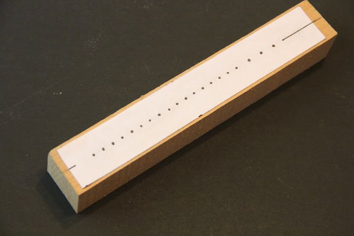
The tracker bar is the single most accuracy-critical wooden part in the organ. It is a strip — a school ruler in John Smith’s “readily-available materials” ethos, or a milled length of close-grained hardwood in a considered build — drilled with one small hole per note, spaced to match the roll exactly. If the holes wander even a fraction of a millimetre off the roll’s track centres, notes read late, early, weakly, or as neighbours; there is no downstream adjustment that fixes a mis-drilled bar (Senger, COAA #24; Wright, melright.com/busker).
6.2.1 Stock
John Smith’s plans nominate a hardwood school ruler — flat, stable, already finished, and free. Senger’s caution is about splitting: maple beats walnut because walnut’s open grain splinters at the hole edges when the drill breaks through, ragging the sealing face the paper must ride on (Senger, COAA #24). Any stable, close-grained hardwood of similar section (roughly 25–30 mm wide × 5–6 mm thick, est., matching a ruler) works if it is dead flat; the roll seals against this face, so a warp or a rise anywhere along it lets that note leak or mistrack.
6.2.2 Hole sizes
The tracker holes are small — the paper only has to admit a control puff, not a pipe’s full wind, on a valved organ — but two sizes are used:
Table 1 — pipe's full wind, on a valved organ — but two sizes are used
| Track | Diameter | Reason |
|---|---|---|
| Melody notes | 4 mm | Enough signal air to inflate a pouch briskly; small enough to seal under the paper reliably |
| Lowest bass notes | 6 mm (original) | Larger air appetite of the bass; later plan revisions kept them at 4 mm by lengthening the bass tracker holes into slots instead of widening them (Senger, COAA #24; Wright) |
On the valveless Basic 20, the same 4 mm / 6 mm split exists for a blunter reason: there the hole passes the pipe’s entire wind, so the bass genuinely needs the extra area (see the valveless section). On the valved Universal the holes only pass signal air, which is why the plan could later shrink the bass back to 4 mm by making the hole a longer slot — more open time per perforation rather than more open area (Wright, melright.com/busker).
The roll runs on ~110 mm stock and the bar is laid out on 31-note Raffin spacing even though only 20 (or 26) holes are cut, so the bar is compatible with commercially punched Raffin-scale rolls (Senger, COAA #24; Beckman, COAA #31). The centre-to-centre track pitch on that standard is on the order of 4–5 mm (est.); the builder does not guess it — the plan supplies the exact cumulative-dimension table, and that table, not a ruler laid hole to hole, is what the bar is drilled from.
6.2.3 Drilling accurately: the cumulative-dimension method
The classic beginner’s error is to measure each hole from the last one. Small per-hole errors then accumulate: twenty holes at +0.1 mm each put the top note 2 mm out of register, which is a wrong note. The fix, emphasised by every John Smith source, is to work from a single datum:
- Build a cumulative-dimension spreadsheet — the position of every hole measured from one end of the bar (hole 1 at X mm, hole 2 at X + pitch, hole 3 at X + 2·pitch …), never hole-to-hole. Errors then cannot compound; each hole is independently referenced to the datum (Senger, COAA #24).
- Set that datum against a drill-press fence. The bar slides along the fence and each hole’s position is set with a steel rule (not a tape) read from the same zero. A stop block on the fence makes each cumulative distance repeatable.
- Use a brad-point (lip-and-spur) bit so the point registers the centre before the flutes cut — a twist drill wanders on entry and will not hold the line.
- Back the bar with scrap so the bit breaks through into waste, not into open air; this is what prevents the exit-side splintering that ruins the sealing face (Senger, COAA #24).
6.2.4 The saw-kerf alignment trick and the honeycomb
Two builder tricks make the bar both accurate and connectable.
The saw-kerf alignment trick puts a shallow saw kerf down the length of the bar as a continuous reference line before any hole is drilled. Because every hole is then centred on that one kerf, the whole row shares a single straight datum edge rather than depending on the drill-press table staying square hole to hole; the kerf also gives the paper a slight, consistent lead-in across the row so all notes read alike (Wright, melright.com/busker; builder practice). It is the lateral counterpart of the cumulative spreadsheet: the spreadsheet fixes hole spacing along the bar, the kerf fixes hole alignment across it.
The honeycomb solves a packaging problem. The holes sit on ~4–5 mm centres — far too tight to fit a nipple or a tube behind each one. So the back of the bar (or a block immediately behind it) is relieved into a honeycomb: a fanned gallery of individual channels, one per note, that each start at a tracker hole on the tight roll pitch and fan out to a wider spacing where a nipple can actually be fitted and a tube run without crowding its neighbour (Beckman, COAA #31; Wright). Each channel is isolated from the next so notes cannot cross-talk. The honeycomb is what physically converts the dense row of reading holes into a spread-out manifold of tubing take-offs.
6.3 The pouch-and-valve chest (valved: Universal / 26-note)
Everything to this point delivers a puff of signal air out of a honeycomb nipple. The chest is where that signal becomes pipe wind. Vol 02 §5 walked the rest → trigger → speak → release cycle; this section builds the box that does it.
6.3.1 The laminated valve chest
The chest is a pneumatic circuit board. It is a lamination:
- a 1/4” particle-board core, into which the wind channels are router-cut before assembly; sandwiched between
- two 1/8” Masonite (hardboard) skins, glued on to close those routed grooves into enclosed passages (Beckman, COAA #31).
Routing the channels into the core and then capping them is what makes the distribution airtight and flat — there are no glued-up wall joints inside the wind path to leak, just a smooth-faced hardboard lid over a routed groove, the same principle as a routed pneumatic “motherboard” in a player piano. One set of channels carries pressure-box wind to every valve seat; another carries each valve’s output to its pipe-supply nipple. Because the core is only 1/4” thick, the router is set shallow and the grooves are generous in width rather than depth to keep flow resistance low.
Tip: Cut and de-burr every channel, dry-fit, and prove the routing before gluing the skins on. Once the Masonite is bonded, a mis-routed or fuzzy channel is buried for good. Sanding the core dead-flat before lamination matters more than it looks: a 1/8” skin will telegraph and leak over a proud ridge.
6.3.2 The pouch board
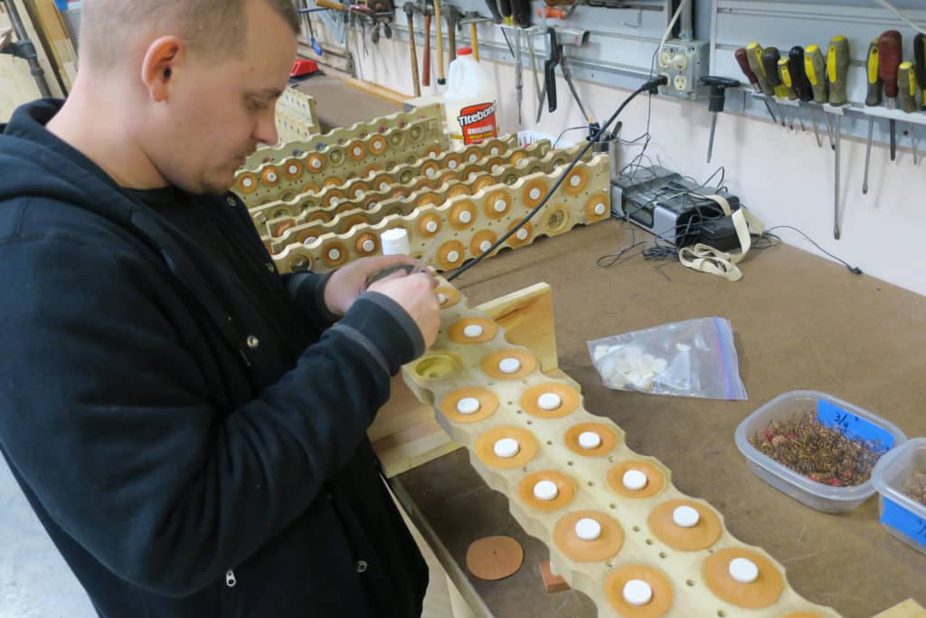
Under the valve box sits the pouch board, drilled with one pouch well per note. Over each well is glued a pillow pouch of zephyr skin or thin leather — a small, supple diaphragm that lies flat when the well is unpressured and swells like a pillow when signal air fills the well beneath it (Beckman, COAA #31; general pouch-action practice, Wright, melright.com/busker). Zephyr skin (a very thin, airtight leather) is preferred because it is light and low-hysteresis: it inflates fully on a small pressure and, crucially, collapses cleanly when the well is vented, which is what a fast note release demands. Pouches are glued down airtight around their rim — fish glue or hide glue, worked so the leather is stuck but not stiffened at the flexing zone.
6.3.3 The valves
Above each pouch, in the valve box, sits the valve itself:
- a 1/4” poplar dowel as the valve body — light, straight-grained, and stable;
- faced on its seating end with a leather punching (a small leather disc) that seals soft against the seat; and
- carried on a 1/8” brass rod stem that guides it to lift straight up off the seat and drop straight back (Beckman, COAA #31).
The pouch pushes on the bottom of the stem; the stem lifts the dowel; the leather face clears its seat and box wind flows past it, up the chest’s output channel, and out the pipe-supply nipple. When the pouch collapses, the valve reseats under its own light weight plus the wind pressure bearing on it. Poplar for lightness, leather for a silent airtight seat, and a brass stem for a straight, low-friction guide: each material choice serves the reset, because a valve that is heavy, sticky, or crooked hangs open.
6.3.4 The adjustable bleed — why it earns its keep
Each pouch well carries a small bleed: a deliberate, permanent leak from the well to the box’s low side (or atmosphere). Vol 02 §5 explained why it exists; the build point is that on the John Smith valved action the bleed is adjustable — sized on the bench, per note, typically by a small set screw, needle, or interchangeable orifice at the well (Beckman, COAA #31). It has to be adjustable because the ideal size is not a single number:
- Bleed too large → the well never reaches full pressure, the pouch inflates weakly, and the valve lifts late, partially, or not at all. The note is soft, slow, or silent — the leak is stealing the signal it is meant only to vent.
- Bleed too small → the well cannot dump quickly when the perforation passes, the pouch stays inflated, and the valve hangs open. The note ciphers — drags on after the paper has closed the hole.
The correct bleed lets the well pressurise decisively on a puff of signal air yet collapse cleanly the instant the paper re-covers the hole. Since the right value depends on pouch stiffness, valve weight, well volume, and the tracker hole/tube size feeding it, it is set by ear and by watching the roll: open it until notes release crisply without dragging, then no further. Chasing hung notes and setting bleeds is revisited as a voicing task in Vol 10.
6.3.5 Nipples and tubing
The wind paths between subassemblies are joined by nipples and tubing. The plan’s considered version presses brass nipples into the honeycomb take-offs, the pouch-board wells, and the pipe-supply channels, and connects them with neoprene tubing — flexible, airtight, and re-routable, so a tube can be pulled and re-seated when chasing a leak (Beckman, COAA #31). The original economy version dispenses with brass and simply glues vinyl tube directly into the drilled holes (Beckman, COAA #31). Brass-and-neoprene is more work and more money but is serviceable; glued-in vinyl is cheaper and lighter but permanent — a cut-and-reglue job to change. Either way the tube runs must be kept short, snag-free, and unkinked: a pinched signal tube inflates its pouch sluggishly and softens or delays that one note, indistinguishable at the pipe from a bad bleed until the tube is traced.
6.4 The valveless contrast (Basic 20)
The Basic 20 deletes the entire chest just described. There is no pouch board, no valve box, no laminated distribution core, no bleed — “the paper roll and the tracker bar are the valves” (Senger, COAA #24; johnsmithbusker.co.uk). Each tracker hole is tubed straight to a pipe foot. When a perforation opens the hole, box wind flows directly down the tube and blows that pipe; when paper re-covers the hole, the pipe stops. The build collapses to the pressure box, the tracker bar, and one tube per pipe.
The trade-offs are hardware-real:
Table 2 — The trade-offs are hardware-real
| Valveless (Basic 20) | Valved (Universal / 26) | |
|---|---|---|
| Parts per note | 1 tube | pouch + valve + stem + seat + bleed + channels |
| Wind to the pipe | squeezed through the small paper hole | drawn full-bore from the box |
| Bass | needs enlarged 6 mm holes to feed thirsty pipes | 4 mm signal hole feeds a full-flow valve |
| Response | limited by paper sealing full pipe wind | pouch amplifies a light signal; crisper, more repeatable |
| Ranks / stops | one direct rank; no rank gating possible | multiple ranks; stops gate whole ranks (Vol 05) |
| Build reach | a weekend handyman can finish it | a leathering-and-bench project |
The single deepest consequence is the last two rows. Because a valveless pipe must pull its entire wind through a paper-sized hole, the hole diameter caps how big — how loud, how low — a pipe can be, and there is no wind headroom left to add a second, third, or fourth rank. And because the paper hole feeds exactly one pipe with no intermediate stage, there is nowhere to insert a stop: a stop works by gating box wind to a whole rank upstream of that rank’s valves (Vol 05 §“The four stops”), and a valveless organ has no valves and no rank to gate. The Basic 20 is therefore permanently one voice at full volume whenever a hole opens. Everything the Universal’s chest costs in pouches, valves, and bleeds, it buys back as four melody stops, bass with octave helpers, an optional glockenspiel, and registration — the pneumatic amplifier is exactly what makes a four-stop organ playable from one 20/26-note roll.
Warn: The chest is the Universal’s reward and its tax. Every note now owns a pouch to leather, a well to drill, a valve to seat, a stem to align, and a bleed to set — 20 or 26 times over, plus the ranks. A single sticky valve, hardened pouch, pinched tube, or mis-set bleed is one wrong note, and the fault is inside a glued-up laminated box. Build the chest so it can be reached: leave the valve box removable and the pouch board accessible before the pipes go on top.
6.5 Building order and airtightness (pointer)
Because the chest is buried under the pipework once assembled, the sequence matters: prove the pressure box airtight; drill and fit the tracker bar and its honeycomb; router, dry-fit, and laminate the valve chest; leather the pouches and prove each well holds; fit, align, and seat the valves; tube the honeycomb to the pouch board; then wind the whole action before a single pipe is mounted and watch for pouches that won’t inflate, valves that hang, and wells that leak. The full realistic assembly order, the trial-fit checks, and the common interference problems are Vol 09; first wind and bleed-setting are Vol 10.
Sources
- Beckman, “John Smith Universal (20/26) Organ,” Carousel Organ #31 (COAA) — the valved chest: 1/4” poplar-dowel valves faced with a leather punching on 1/8” brass rod stems; pillow pouches of zephyr skin / leather on a pouch board; adjustable bleeds; the laminated valve chest (1/4” particle-board core between two 1/8” Masonite skins, wind channels router-cut before lamination); brass nipples + neoprene tubing (with the original glued-in-vinyl alternative); the fanned honeycomb behind the tracker bar; ~110 mm roll.
- Senger, “Building the John Smith Organ,” Carousel Organ #24–25 (COAA) — the pressure box as “the heart / mechanical backbone” (roll transfer, tracker bar, crankshaft supports, take-up drive, disengage lever, Lexan-windowed sealed lid); operating pressure ~5 in H₂O; tracker holes 4 mm with the lowest bass 6 mm (later kept at 4 mm by lengthening the hole into a slot); 31-note Raffin spacing, 20 holes; the cumulative-dimension method, drill-press fence, steel rule, brad-point bit, backing to prevent breakout, maple over walnut for splitting; contact cement ≈ 2× silicone for the window.
- Wright, melright.com/busker (Melvyn Wright’s John Smith pages) — tracker-bar making and hole registration; valveless operation (paper + tracker are the valves; pipes blown directly; enlarged bass holes for greater air consumption); the saw-kerf datum and honeycomb as builder practice.
- johnsmithbusker.co.uk (John Smith / Roll Cutter) — the valveless design’s simplicity as the range’s selling point; ready-made tracker bars and leather among the supplied parts.
- edgaida.com (Ed Gaida) — reference photographs of a valved John Smith pouch board and valve chest.
- General organ pouch/valve/bleed action (a perforation admits wind to a pouch well, the pouch lifts a valve off its seat, an adjustable bleed resets the well after the perforation passes) corroborated against standard pressure-pneumatic windchest-action practice.
Cross-references: the wind system (feeders, three-lobed crankshaft, reservoir, spring, spill valve, manometer, ~5 in H₂O) in Vol 04; the four flute ranks, bass pipes/helpers, glockenspiel, and the stop action that gates whole ranks in Vol 05; the end-to-end air path and the rest → trigger → speak → release valve cycle in Vol 02; the roll-drive train, take-up spool, and rewind/disengage lever that also live in this pressure box in Vol 07; the 20- and 26-note scales and the tracker-bar hole map in Vol 03; assembly order, airtightness testing, and interference fixes in Vol 09; first wind, leak chasing, and bleed-setting in Vol 10.
Comments (0)