John Smith Universal Organ · Volume 4
The John Smith Universal — Vol 04: The Wind System (Build & Theory)
This volume develops the part of the Universal that Vol 02 §“Air path” only sketched: how a pulsing hand crank is turned into a steady, regulated column of low-pressure air that the pipes can be voiced and tuned against. Vol 02 traces the whole chain (crank → feeders → reservoir → pressure box → tracker bar → pouch/valve → pipe) as a block diagram; here the feeder bellows, the crankshaft that drives them, the reservoir, its pressure-setting spring, and the spill valve are treated as a coupled pneumatic-mechanical system, with build detail and the numbers that matter. The pressure box and the pouch/valve action it feeds are Vol 06’s subject; the interplay between wind pressure and voicing — why a pipe that speaks cleanly at one pressure over-blows or goes dull at another — is developed in Vol 10. This volume stops at the wind delivery hose that hands regulated air to the pressure box.
Voice/units note. All pressures are stated in inches of water column (in H₂O) with metric and psi equivalents; spring, cloth, and timber dimensions carry units throughout. Values drawn from the two COAA build articles are cited inline as (Senger, COAA #24–25) and (Beckman, COAA #31); community sources (Melvyn Wright’s John Smith pages, the Busker Organ Forum) are cited by name. Figures the sources do not pin down are marked (est.) and never invented.
4.1 The design problem: constant pressure from a pulsing crank
A flue pipe’s pitch, loudness, and tone all move with the wind pressure that drives it. A pressure that sags on each up-stroke of the operator’s arm and surges on each down-stroke would make the whole rank waver in pitch and volume in step with the cranking — the sound of a poorly winded barrel organ. The wind system’s entire job is therefore regulation: convert the intermittent, direction-alternating output of hand-pumped feeders into an air supply that holds close to a single set pressure regardless of how many pipes are speaking or how evenly the operator cranks.
The Universal, like essentially all street and fairground organs, solves this with the classical two-stage arrangement: feeders (the pumps) charge a spring-loaded reservoir (the store and the regulator), and a spill/relief valve dumps any surplus so the reservoir never drives the pressure past its set point. “Small as well as big street organs are usually powered from bellows, agitated from a hand-operated crankshaft, with the bottom two wedges constituting a double-acting feeder with valves for the air into the top, spring-loaded reservoir” is the canonical description of the layout (fonema.se, Pushing and bouncing air), and the John Smith designs follow it exactly. The John Smith target operating pressure is 5 in H₂O (Senger, COAA #24–25); the manometer to measure it is part of the published plans.
Table 1 — 1. The design problem: constant pressure from a pulsing crank
| Pressure, expressed several ways | Value |
|---|---|
| Operating pressure (target) | 5 in H₂O |
| Millimetres of water | 127 mm H₂O |
| Pascals / kilopascals | ≈ 1245 Pa (1.25 kPa) |
| Pounds per square inch | ≈ 0.181 psi |
| Millibar | ≈ 12.5 mbar |
(Conversions: 1 in H₂O ≈ 249 Pa ≈ 0.0361 psi at ~20 °C. The point of the table is the scale of the numbers — organ wind is a fraction of one psi. General organ practice runs 2–5 in H₂O for small instruments (organforum.com; risterpipeorgans.com), so the Universal sits at the upper, brighter end of that band.)
4.2 The feeder bellows
4.2.1 Geometry and covering
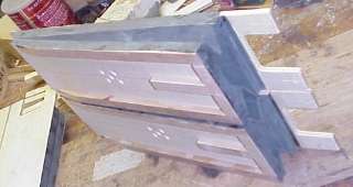
Each feeder is a wedge (single-fold) bellows: two roughly triangular or rectangular wooden boards hinged along one edge, joined around the other three edges by a flexible airtight gusset so the enclosed volume changes as the free board swings. On the pull stroke the feeder inhales through an inlet flapper; on the push stroke that flapper seats shut and the air is forced out through an outlet flapper into the reservoir — a one-way pump (fonema.se). The flapper valves are simple leather-faced flaps hinged over ports and held lightly closed; John Smith specifies Columbia CGL Valve-Heavy leather for them (Senger, COAA #24–25). The whole point of a feeder is that it need not be particularly airtight against back-pressure the way the reservoir must — its flappers do the sealing directionally.
The gusset is the flexing cloth (or leather) that walls the wedge. John Smith’s “readily-available materials” ethos shows here most clearly: the bench-standard covering is Columbia CPL Gusset Medium leather, but his economy substitute is ordinary blackout curtain cloth — the rubberised/coated domestic fabric — which is airtight, cheap, and folds well (Senger, COAA #24–25; Melvyn Wright, John Smith pages). Leather gives the longest life and the best feel; blackout cloth brings a full-size organ into reach of a builder unwilling to spend on hides. Either way the covering is glued to the boards with Fish Glue for the leather-to-wood joints (Senger, COAA #24–25), and the corners are reinforced with small leather patches because the corner is where three fold lines meet and where a cloth-only gusset first splits and leaks.
4.2.2 Internal stiffeners and the classic mistake
A wedge gusset that is simply a limp cloth wall will billow outward under pressure and suck inward under vacuum, wasting stroke and flapping audibly. The fix, standard in organ-building, is to glue thin internal stiffeners — light wooden ribs or stiff card — into the gusset partway up each side so the cloth folds along a controlled hinge line instead of ballooning. The Universal’s feeder gussets carry such stiffeners.
Warn — the fold-binding mistake. The classic beginner’s error is placing the stiffener too close to the fold (the moving hinge). When the bellows closes, a stiffener set near the crease jams against the opposing board or against the fold itself before the feeder has fully collapsed, so the boards bind — the stroke stops short, the pump loses displacement, and the crank develops a hard spot. The stiffener must sit far enough from the fold that the gusset can pleat around it freely through the whole stroke. This is the single most common cause of a stiff, short-stroking home-built feeder (Busker Organ Forum, bellows threads; Melvyn Wright, John Smith pages).
4.3 Feeder count: the Universal’s three feeders vs the Basic 20’s two
The John Smith range does not use one feeder arrangement. The two the reader will meet are the Basic 20-Note’s double feeder and the Universal’s triple feeder, and they differ in how smooth the delivered wind is before the reservoir even gets to regulate it.
4.3.1 The Basic 20-Note: double bellows, two connecting rods
The valveless Basic 20 uses a double (double-acting) feeder pair driven by a crankshaft through two connecting rods. The crank throws two arms 180° apart (“arms opposite!” is the build note, and the crankshaft is welded up on a jig to guarantee it) so that one feeder fills the reservoir while the other is re-filling itself (Senger, COAA #24–25). The result is a partly self-smoothing pump: because the two feeders are in anti-phase, there is a delivery stroke for much of every revolution, and the reservoir has less peak-to-peak fluctuation to absorb than a single feeder would present. The Basic 20’s crankshaft is 1/2 in (12.7 mm) steel rod with welded flat-steel throws (Senger, COAA #24–25).
4.3.2 The Universal: three feeders on a three-lobed crankshaft
The Universal steps up to three feeder bellows driven by a three-lobed crankshaft, the lobes spaced 120° apart (Beckman, COAA #31). Three feeders phased at 120° deliver an even smoother, more continuous flow than the two-feeder pair: as one feeder passes through the dead spot at the end of its delivery stroke, another is already mid-delivery, so the summed feeder output has a smaller ripple and never fully drops to zero within a revolution. Less ripple into the reservoir means the reservoir spring and spill valve have less work to do, and the delivered wind is steadier for the same cranking effort — worth the extra feeder on a valved organ whose four ranks make wind demand higher and more variable than the Basic 20’s.
The Universal’s crankshaft is a composite: a 5/16 in (7.9 mm) steel rod for the running shaft with the throw offsets built up from 1/4 in (6.4 mm) aluminium bar, the lobes located and bonded with Loctite 680 (a high-strength retaining compound) and pinned with spring pins so the joints cannot creep under load (Beckman, COAA #31). This is a deliberately amateur-friendly construction — no welding jig, no machine shop — that still yields three accurately phased throws.
4.4 The reservoir
4.4.1 What it is and where it sits
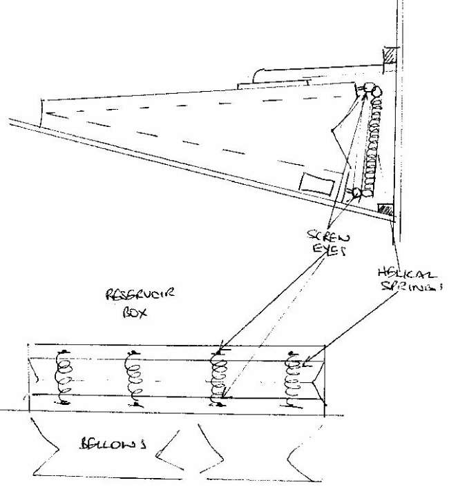
A single reservoir sits directly on top of the feeders (Senger, COAA #24–25). It is itself a bellows — the same wedge or box construction, same gusset craft as the feeders — but with two differences of function. First, it has no pump stroke driven by the crank: it floats freely, opened by incoming air from the feeders and closed by its own spring, so its instantaneous position is a running average of supply and demand. Second, it must be genuinely airtight in both directions, because it is the pressure store; a reservoir that leaks cannot hold a set pressure between feeder pulses. On the Universal the reservoir also serves as a shelf: the five bass “helper” pipes (tuned an octave above the mitred bass pipes) are mounted on top of it (Beckman, COAA #31).
The reservoir performs three jobs at once: it stores enough air to bridge the gaps between feeder deliveries and to meet a sudden chord; it regulates the pressure through its spring; and, with the spill valve, it caps the pressure.
4.4.2 The spring that sets the pressure
The reservoir’s pressure is set by the force its spring exerts on the moving board divided by that board’s area. Increase the spring force and the pressure rises; the reservoir will hold whatever pressure makes the air force on the board balance the spring. John Smith’s specified spring is a heavy music-wire (spring-steel) spring (Senger, COAA #24–25). In the “readily-available materials” spirit, his celebrated economy substitute is an ordinary office binder clip, whose sprung wire loops supply enough force on a small reservoir to reach working pressure (Senger, COAA #25; the binder clip appears on John Smith’s own materials list).
Builders use two spring topologies, and it is worth understanding both because they behave differently:
- A single heavy compression/leaf spring bearing on the reservoir board (John Smith’s baseline). Simple, but its force — and therefore the pressure — changes slightly as the reservoir moves through its travel, so the pressure is only approximately constant across the reservoir’s stroke.
- Four small tension springs across the open end of the bellows. A widely recommended alternative: it is easy to fit, the pull is symmetric, and — a real practical advantage — the whole reservoir/spring assembly can be removed and refitted in one piece for service (Melvyn Wright, reservoir-springs page; general search corpus). Choosing longer, softer springs working over a small fraction of their range keeps the force (and pressure) more nearly constant across the reservoir stroke than one stiff spring does.
The spring is tuned empirically against the manometer (see §6): the builder adjusts spring tension — bending a leaf, adding/removing binder clips, or re-tensioning the four springs — until the reservoir floats mid-travel at 5 in H₂O under a representative load, then trims the spill valve to cap it there.
Table 2 — 4.2 The spring that sets the pressure
| Reservoir spring — options and behaviour | Detail |
|---|---|
| John Smith baseline | Single heavy music-wire spring on the reservoir board |
| Economy substitute | Office binder clip (readily-available-materials ethos) |
| Recommended alternative | Four small tension springs across the bellows end |
| Sets pressure to | 5 in H₂O (≈ 127 mm, ≈ 1.25 kPa, ≈ 0.18 psi) |
| Adjustment method | Empirical, against the water manometer in the plans |
| Constant-pressure tip | Soft/long springs over a small stroke fraction → flatter force curve |
4.5 The spill / relief valve and the limit block
The spring alone would hold pressure only if the feeders delivered exactly the air the pipes consume. They do not — feeder output varies with cranking speed, and pipe demand jumps when a chord speaks and collapses when the roll goes silent. Without a relief path, over-supply would inflate the reservoir until the spring force (and the pressure) climbed past the set point and the organ sharpened and over-blew. The spill/relief valve is what makes the pressure a cap rather than a coincidence.
The John Smith relief valve is a sprung flap: a leather-faced flap covering a port in the reservoir, held closed by a light spring (Beckman, COAA #31; fonema.se). Its holding spring is set so the flap stays seated at and below the target pressure and lifts to vent surplus air the instant the reservoir tries to exceed it — “a heavy spring that lets air out of the reservoir if the pressure gets too high… helps maintain a relatively constant pressure” (search corpus; fonema.se, Pushing and bouncing air). Because the flap is held down against the internal pressure, the holding spring force must exceed the pressure force on the flap’s face; that is the design constraint that sizes the spring.
The forces involved are genuinely small, which is why a light spring suffices. For a 1 in (25.4 mm) diameter relief port (face area ≈ 0.785 in²):
Table 3 — a 1 in (25.4 mm) diameter relief port (face area ≈ 0.785 in²)
| Relief-valve face force (1 in dia port, area ≈ 0.785 in²) | Force |
|---|---|
| At 5 in H₂O (0.181 psi) — the Universal set point | ≈ 0.14 lbf (≈ 0.63 N) |
| At 8 in H₂O (0.289 psi) — a typical small-organ figure | ≈ 0.23 lbf (≈ 1/4 lb) |
(The 8 in / 1 in / ~1/4 lb worked example is the community rule of thumb — “about 1/4 pound of force on the valve facing” at ~8 in H₂O on a 1-inch valve (search corpus; Busker Organ Forum). Scaled to the Universal’s 5 in H₂O the face force falls to ~0.14 lbf, so the relief spring is genuinely light — a few ounces of force is enough to hold it shut, and only a whisker more opens it.)
A limit (stop) block works with the valve to bound the reservoir’s travel. When the reservoir is fully charged and pipe demand is low, the reservoir board rises until it either forces the spill valve open or meets its travel stop; the block prevents the reservoir from over-inflating and over-tensioning its own spring past the set pressure. Together the spring (which sets pressure), the spill valve (which dumps surplus to cap it), and the limit block (which bounds travel) hold the delivered wind close to constant across the working range of cranking speeds and pipe loads.
4.6 Measuring the pressure: the water manometer
The plans include a water manometer (Senger, COAA #24–25) because the wind system cannot be set by feel. A manometer is the reference instrument for organ wind: a U-shaped clear tube part-filled with water, one leg open to atmosphere and the other teed into the wind supply. The wind pushes the water down its leg and up the open leg; the difference in the two water levels, read in inches, is the pressure in inches of water — which is precisely why organ pressure is quoted in in H₂O in the first place (organforum.com; thediapason.com). No gauge calibration is needed; the column is the calibration.
Building and using it is trivial: a length of clear vinyl or aquarium tubing bent into a U and taped beside a ruler, half-filled with water (a drop of food colour makes the meniscus readable). Tee it into the reservoir output or the pressure box, crank the organ to a steady speed, and read the level difference. The Universal is trimmed until that difference holds at 5 in (127 mm) across the working range of cranking speeds — feeder spring, spill-valve spring, and any binder-clip additions are all adjusted against this reading.
Tip — read it under load, not just idling. A wind system can show 5 in H₂O with no pipes speaking and then sag when a full chord opens if the feeders or reservoir are undersized or leaking. Set and verify the pressure with a representative number of pipes playing, and watch that the manometer holds steady rather than bouncing with each crank revolution — a bouncing column points straight back to feeder phasing, a weak reservoir spring, or a leak (Vol 09 covers leak-chasing; Vol 10 covers voicing against a verified pressure).
4.7 Connecting rods, bearings, and wind delivery
4.7.1 Connecting rods and bearings
The crank throws drive the feeders through connecting rods — the Basic 20 uses two (one per feeder), the Universal three (one per feeder, at 120°). Each rod runs from a crank throw to its feeder’s moving board, converting the crank’s rotation into the feeder’s reciprocating pump stroke. The rods and shaft turn in low-friction bearings consistent with the rest of the Universal’s mechanism: UHMW (ultra-high-molecular-weight polyethylene) bearing blocks and bronze bushings are specified for the running gear (Beckman, COAA #31). Both are self-lubricating and quiet — important on an instrument whose whole output is acoustic and where a squeaking bearing would be heard over the music. UHMW blocks in particular are cheap to make and forgiving of the amateur tolerances the design assumes. In John Smith’s readily-available-materials list an English penny even stands in as a crankshaft case bearing (Senger, COAA #25) — a flat bronze disc pressed into service as a plain thrust surface.
4.7.2 Wind delivery to the pressure box
Regulated air leaves the reservoir through a wind delivery hose to the pressure box, the sealed chamber that is the organ’s mechanical backbone and that distributes wind to the tracker bar, valves, and pipes (Vol 06). John Smith again reaches for the domestic hardware store: the delivery duct can be flexible electrical conduit used as an air hose (Senger, COAA #25). A flexible hose (rather than a rigid duct) is deliberate — it lets the reservoir float and the feeders reciprocate without transmitting mechanical vibration into the pressure box, and it tolerates the small relative movement between the bellows assembly and the case. The pressure box itself, its sealed Lexan-windowed lid, and the valve and tracker-bar behaviour it houses are Vol 06’s subject; this volume hands off at the hose.
4.8 Why steady wind is the whole point
Every downstream subsystem inherits the wind system’s regulation quality:
- Pitch stability. Flue-pipe pitch rises with pressure. A reservoir that lets pressure sag and surge with the cranking makes the whole organ warble in pitch in step with the operator’s arm — the tell-tale unsteadiness of a badly winded organ. A reservoir holding a flat 5 in H₂O keeps the pipes at the pitch they were tuned to (Vol 10).
- Even loudness. Loudness also tracks pressure; steady wind means steady volume rather than a pulsing swell on every revolution.
- Voicing that stays true. Pipes are voiced — cut-up, windway, cover position, bass “ears” — against a specific pressure. If the delivered pressure does not match the pressure the pipes were voiced at, they over-blow (too much) or go dull and slow to speak (too little). The wind system and the voicing bench are two halves of one calibration: voice the pipes at the pressure the reservoir actually holds, and hold the pressure the pipes were voiced at. That pressure-voicing interplay — including the slightly-sharp tremolo rank that is deliberately mistuned to beat against its neighbour — is developed in Vol 10.
The measure of a good hand-cranked wind system is that a listener cannot hear the crank in the sound at all: the pitch is steady, the volume is even, and the pipes speak the way they were voiced, whether the operator is turning briskly or has slowed to talk to the crowd. On the Universal that steadiness is bought by three 120°-phased feeders, an airtight sprung reservoir, a light spill valve capping the pressure, and a manometer to prove the number — 5 in H₂O — is really there.
4.8.1 Cross-references
- Vol 02 §“Air path” — the whole-organ block diagram this volume expands (crank → feeders → reservoir → pressure box → tracker bar → pouch/valve → pipe).
- Vol 06 — The Pressure Box, Tracker Bar & Valves — where the wind delivery hose leads; the sealed backbone, pouch-and-valve action, and the valveless contrast.
- Vol 09 — Assembly Sequence — bellows/reservoir build order, airtightness and leak-chasing.
- Vol 10 — Setup, Voicing & Tuning — first wind, voicing flue pipes against a verified pressure, the slightly-sharp tremolo rank, and the manometer tuning rig.
Sources
- Senger, Paul. “Building the John Smith Organ,” Carousel Organ #24 & #25 (COAA). Operating pressure 5 in H₂O and the manometer in the plans; double bellows + single reservoir + two connecting rods; reservoir relief valve + heavy music-wire spring (binder-clip substitute); crankshaft 1/2 in steel + welded flat steel (“arms opposite”); Columbia CPL Gusset Medium / CGL Valve-Heavy leather, Fish Glue; the “readily-available materials” list (blackout cloth, binder clip, English-penny bearing, flexible-conduit air hose).
- Beckman. “John Smith Universal (20/26) Organ,” Carousel Organ #31 (COAA). Three feeder bellows on a three-lobed crankshaft, lobes 120° apart; 5/16 in steel rod + 1/4 in aluminium bar, Loctite 680 + spring pins; sprung spill/relief valve; UHMW bearing blocks + bronze bushings; bass helper pipes on top of the reservoir.
- Melvyn Wright, John Smith Busker Organ pages (melright.com/busker) — bellows construction, reservoir springs (four-tension-spring alternative, removable assembly), spill valve, curing air leaks.
- Busker Organ Forum (tapatalk.com/groups/buskerorgan) — relief-valve sizing rule of thumb (~1/4 lb face force at ~8 in H₂O on a 1 in valve); the stiffener-too-near-the-fold binding failure.
- fonema.se, Pushing and bouncing air — the double-acting feeder + spring- loaded reservoir layout of street/crank organs; the relief-spring-holds-pressure description.
- General organ-wind references (organforum.com; risterpipeorgans.com; thediapason.com; organsupply.com) — small-organ wind pressures (2–5 in H₂O), reservoir/curtain-valve regulation, and the U-tube water manometer as the reference pressure instrument.
Comments (0)