Hammond B-3 · Volume 10
Hammond B-3 — Vol 10: The Vibrato/Chorus Scanner & Run Box
The Hammond vibrato/chorus system is the most mechanically intricate signal-processing path in the console. Where every other signal path in the B-3 is purely passive copper and wire until it reaches the AO-28’s tubes, the vibrato path runs through a spinning rotary variable capacitor (the scanner) sweeping a tapped LC all-pass delay line (the line box) to produce the organ’s characteristic pitch-modulation and chorus effects. The scanner mechanism is driven off the same synchronous run motor that spins the tonewheel generator, and it is acknowledged throughout the trade as the single hardest Hammond repair — the wax and fiber insulators absorb moisture and oil, conductive metallic whiskers grow inside the housing, and disassembly/reassembly requires care that cannot be rushed.
The player-facing controls — V1/V2/V3 and C1/C2/C3 selector, the Swell and Great vibrato tablets, and the musical character of each setting — are covered in Vol 03 §“Vibrato & chorus (the scanner)”. This volume is the service-level complement: mechanism, theory, failure modes, diagnosis, and bench procedure. Cross-references: Vol 02 (signal-path theory and synchronous motor); Vol 03 (player-facing controls; vibrato/chorus character); Vol 06 (safety prerequisites — discharge procedure, mains hazards); Vol 07 (run motor, of which the scanner is a mechanical extension); Vol 08 (AO-28, where the vibrato circuit’s input and output connect); Vol 18 (reference and bibliography).
Warn: The scanner assembly sits inside the B-3 console chassis alongside the AC mains supply and the AO-28 B+ rail (approximately +200 VDC). All scanner and line-box service must be performed with the organ unplugged and the AO-28/power-supply filter capacitors discharged and confirmed at 0 VDC per Vol 06 §“Capacitor-discharge procedure.” No work on the scanner or line box may be performed on a live console.
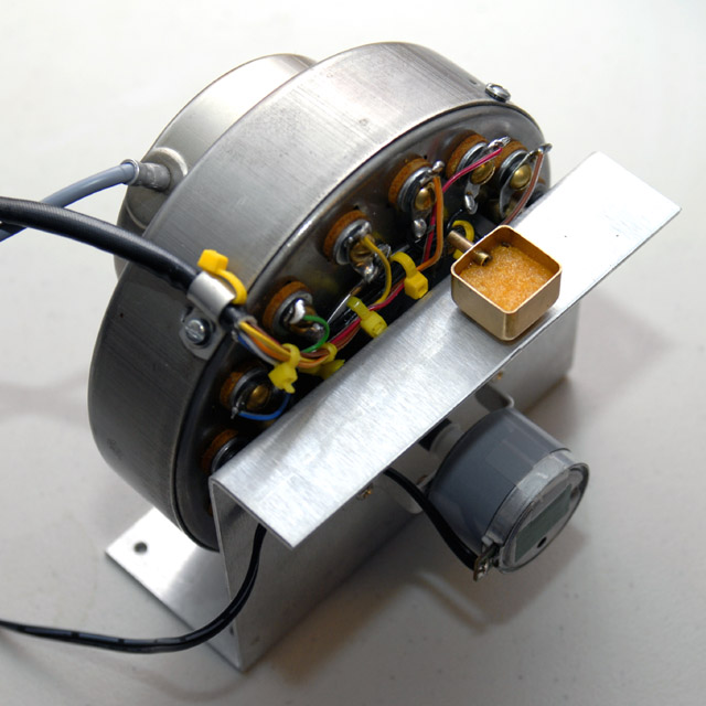
10.1 What the scanner does
The vibrato/chorus system inserts a swept phase delay into the audio path. Phase delay shifts the relative timing of frequency components without attenuating them. When that delay is swept continuously back and forth, the instantaneous pitch of the output oscillates above and below the unshifted pitch — this is vibrato. When the swept signal is mixed back with the unshifted (dry) signal, their phase relationship cycles continuously, producing the characteristic shimmering interference that defines the Hammond chorus (C positions). The mixing of swept and dry is not an equal-level blend; the balance and the depth of the sweep together shape the chorus character.
The player controls (V1/V2/V3, C1/C2/C3, Swell/Great tablets) are documented in Vol 03 §3.4. From the service standpoint, the key distinction is: any fault in the scanner or line box affects both manuals simultaneously, since both manuals share the same scanner and delay line. A fault isolated to one manual’s vibrato — Great works, Swell does not, or vice versa — points to the vibrato tablet contacts or AO-28 routing network (Vol 08, Vol 09), not the scanner.
Warn: A vibrato fault that is isolated to a single manual — vibrato present on Great but absent on Swell, or vice versa — is almost always a failed vibrato tablet contact or a fault in the AO-28 routing, not a scanner or line-box fault. Eliminating the tablet and AO-28 routing (Vol 08 §“Vibrato absent on one manual” fault table) before removing the scanner avoids unnecessary disassembly of the hardest-to-reassemble component in the console.
10.2 The line box (LC delay line)
The line box is the LC network that provides the phase delay the scanner samples. It is a ladder network of air-core inductance coils and wax-paper dielectric capacitors (original) connected as a series of low-pass all-pass filter sections, each section adding a small increment of phase delay to the signal (Hammond B-3/C-3 Service Manual; bentonelectronics.com, “Service Manual — The Hammond Vibrato”). The B-3/C-3 console uses an 18-section coupled-coil delay line — a more compact design than the 25-section line used in earlier non-selective Hammond models and spinets (Hammond B-3/C-3 Service Manual; bentonelectronics.com).
Each filter section adds a phase delay of approximately 50 µs (est.) across the audio band (this figure is documented for the Hammond M-100 spinet’s 16-section line, which uses a comparable topology — stefanv.com, “Overhauling and Improving the Hammond M-100 Series Vibrato System”; the console’s 18-section coupled-coil design may differ and the service manual does not state a per-section delay explicitly). The total delay at full scan (V3/C3) is therefore on the order of approximately 800–900 µs (est.), approaching the ~1 ms full-scan figure cited by electricdruid.net, which describes the line as producing a delay “of around 1 ms (est.)” at full scan. The service manual does not give an explicit total delay. (Vol 03 §“Vibrato & chorus” states a total swept delay of approximately 1 ms (est.) at maximum depth, consistent with the electricdruid figure and the M-100-derived estimate here; all figures are (est.) as the B-3/C-3 service manual does not publish an explicit total delay.)
The delay line has 16 tap points along its length, each wired to one of the 16 stationary scanner plates, connected via wiring from the line-box terminal strip. The 16 stationary scanner plates are wired to these taps in an arrangement that produces a triangular (ascending-then-descending) sweep of the delay as the rotor completes one revolution: one full rotation of the scanner = one complete back-and-forth sweep of the delay taps = one vibrato cycle at approximately 6.9 Hz (est.) (dairiki.org HammondWiki, “Vibrato”; electricdruid.net; b3world.com, “Hammond Technical Information — Vibrato”). The rate is fixed by the synchronous run motor at 412 rpm; it cannot be adjusted by the user (Vol 07 §“The run motor”).
Note: The exact capacitance and inductance values of the 18-section console line box must be read from the unit’s own Hammond B-3/C-3 Service Manual schematic. The M-100 spinet delay line uses a 16-section version with capacitors documented at approximately 0.0056 µF (5.6 nF) for 15 sections and 0.0027 µF (2.7 nF) for the final section, rated at 200 V, with replacement polypropylene types specified at ≥ 630 V (stefanv.com, “Overhauling and Improving the Hammond M-100 Series Vibrato System”). These M-100 values are cited as a reference class only — B-3/C-3 console values may differ and should not be assumed from M-100 data. No line-box component value has been invented for this volume.
10.2.1 How aging wax capacitors distort the vibrato
The original line-box capacitors use wax-impregnated paper dielectric construction. The wax seal is imperfect; the paper absorbs moisture over decades. The result is a systematic increase in capacitance: field measurements on M-100 vintage wax capacitors have recorded values ranging from 41 % to 91 % over specification, averaging approximately 69 % over specification (stefanv.com, “M-100 Vibrato”). The same aging mechanism applies to the console line box. Over-capacitance reduces each section’s filter cut-off frequency, altering the delay profile and introducing amplitude modulation alongside the intended phase modulation — the audible result is a chorus or vibrato with a noticeable tremolo component (amplitude wobble) and an irregular, “thumping” character, rather than the smooth pitch sweep of a healthy system.
Warn: The original wax-paper line-box capacitors must not be used as a reference for capacitance when checking the line box in circuit — after six or more decades they have likely drifted 40 % to 90 % above nominal. Using the drifted original value as the “correct” figure will result in a rebuilt line box that is itself out of specification. Always read replacement values from the service-manual schematic.
10.3 V1–V3 and C1–C3: the service angle
The player-facing operation of V1/V2/V3 and C1/C2/C3 — depth, character, and typical musical use — is documented in Vol 03 §“Vibrato & chorus (the scanner)” and is not repeated here. From the service standpoint, the selector knob controls a switched network in the AO-28 chassis that routes the delay-line input, output, and the dry bypass:
- In V positions, the AO-28 routing connects only the scanned (delayed) signal to the output; the dry signal is not present in the vibrato chain.
- In C positions, the dry signal is tapped off the AO-28 input and summed with the scanned signal to produce the chorus mix.
- V1 / C1 scan approximately one-third of the 18 delay sections (shallow); V2 / C2 approximately one-half; V3 / C3 the full line (Hammond B-3/C-3 Service Manual; dairiki.org HammondWiki, “Vibrato”; Vol 03 §3.4). Fractions are approximate — the service manual describes the selector wiring without expressing the tap positions as exact fractions.
The selector is a multi-position rotary switch on or adjacent to the AO-28 chassis. Common service faults and their service-angle diagnosis:
Table 1 — service faults and their service-angle diagnosis
| Selector fault | Symptom | Probable cause |
|---|---|---|
| No vibrato on any V/C position | Selector open; entire scanner circuit dead | Open switch contact, broken line-box wire, or AO-28 V-2 tube failure (Vol 08) |
| Vibrato on V3/C3 only; V1/V2 produce full-depth vibrato too | V1/V2 tap subset wiring open — V3 (full line) route stays active | Check wiring continuity from selector to V1/V2 tap-subset terminal strip |
| Chorus depth wrong; chorus sounds like pure vibrato | Dry mixing path open or dry coupling cap failed | Probe dry-input path at AO-28; ESR-test dry-path coupling cap |
| Hum added when any V/C position selected | Shielding fault or ground open in scanner cable | Inspect scanner cable shield continuity; verify chassis ground at scanner housing |
| Crackle when selector knob rotated | Oxidised selector switch contacts | Work selector through range; apply contact cleaner safe for plastics (§“Vibrato switch service”) |
Warn: The vibrato selector switch and its associated wiring are on or adjacent to the AO-28 chassis, which carries an approximately +200 VDC B+ rail (Vol 08 §“The AO-28 at a glance”). Probing or re-soldering selector contacts requires the AO-28 to be discharged and confirmed at 0 VDC per Vol 06 §“Capacitor-discharge procedure” before any physical contact. Do not probe the selector area with the chassis live.
10.4 Diagnosing vibrato faults
Because the scanner, line box, AO-28 routing, and run motor are all in the vibrato signal chain, a systematic approach prevents unnecessary disassembly of the most difficult component.
Table 2 — Diagnosing vibrato faults
| Symptom | Probable cause | First diagnostic step |
|---|---|---|
| No vibrato on either manual; all V/C positions dead | AO-28 V-2 tube failure; open scanner wiring; open line-box circuit; failed selector | Audio-probe the AO-28 V-2 plate (Vol 08 §“Signal-tracing”); if signal at V-2 but not at line-box output, fault is in line-box or scanner |
| No vibrato on one manual only | Vibrato tablet contact failure; AO-28 routing open | Check tablet contacts first (Vol 09); probe V-1/V-2 plates in AO-28 (Vol 08) |
| Vibrato present but weak or shallow across all positions | Partial scanner coupling; oil-shorted insulator | Inspect scanner insulators; check selector-to-line-box wiring |
| Vibrato lumpy, uneven, or has tremolo character | Wax caps over-capacitance in line box; partially shorted insulator | Capacitance-test all line-box caps; inspect scanner insulators |
| Vibrato choppy / motorboating / crackling | Zinc dendrite (metallic whisker) growth inside scanner housing | Open scanner and inspect for dendrites (§“Servicing the scanner” step 10) |
| Vibrato depth identical on all six V/C positions | V1/V2 routing open; V3 (full line) always in circuit | Check selector wiring to V1/V2 tap subset |
| Hum or 60 Hz buzz when vibrato engaged | Shielding fault; open ground on scanner cable | Inspect scanner cable shield; verify housing ground connection |
| Scanner rotation slow or absent | Frozen scanner bearing; broken motor coupler spring | Remove motor/scanner assembly; check bearing and coupler springs (§“Removal” below) |
| Squeaking from scanner area during operation | Carbon brush spring tension mispositioned | Open scanner; re-seat brush springs (§“Reassembly” step 16) |
10.4.1 Signal-chain triage sequence
Before removing the scanner or line box, proceed in order:
- Confirm the run motor is running — the scanner cannot rotate until the organ reaches RUN state (Vol 03 §“Start/Run”; Vol 07 §“The run motor”). A faint mechanical whir from the left rear of the console confirms rotation.
- Check both vibrato tablets — engage the Swell tablet, then the Great tablet, individually (Vol 03 §3.4). If vibrato is present on one manual but not the other, fault is in AO-28 routing or a tablet contact (Vol 08, Vol 09).
- Audio-probe the line-box output — with the organ running and a key held, use an audio probe (0.1 µF series capacitor + high-impedance earphone — Vol 08 §“Signal-tracing procedure”) at the line-box output terminal identified on the AO-28 schematic. Sweep the V/C selector through all six positions. If the line-box output sounds wrong (tremolo, irregular depth), suspect the line box. If the line-box output is absent entirely, the fault is upstream (open scanner cable, AO-28 V-2 path failure).
- Visual inspection with power off — with the organ unplugged and discharged: inspect the scanner cable for a broken shield or open conductors; open the scanner housing and inspect for oil on insulators, zinc dendrite whiskers on the housing walls, and whether the rotor turns freely by hand.
Warn: Voltage measurements and audio-probe steps are performed with the organ powered and the AO-28 B+ live at approximately +200 VDC. Keep one hand clear of the chassis; use an insulated audio probe; never contact B+ nodes. Power off, unplug, and discharge to 0 VDC before any physical contact with the scanner assembly or line-box components — discharge procedure: Vol 06 §“Capacitor-discharge procedure.”
10.5 Servicing the scanner
The vibrato scanner is widely acknowledged as the single hardest Hammond repair. Incorrect solvents attack the insulating materials; re-assembling the brush assembly in the wrong order destroys the contacts; over-aggressive handling of the rotor introduces alignment errors. The following numbered procedure is the accepted trade approach, derived from the Hammond Technical Service Bulletin (“Repair and Disassembly of Vibrato Scanners,” via dairiki.org), the dairiki.org rebuild guide (“How To Rebuild The Vibrato Scanner”), and the Benton Electronics vibrato service article (bentonelectronics.com, “Servicing the Hammond Vibrato Scanner”).
Warn: The vibrato scanner contains fiber and Bakelite insulating components that are sensitive to aggressive solvents and heat. Acetone and MEK attack Bakelite and fiber material; heat guns and open-flame drying warp the housing and melt the wax from the fiber insulators. Use only denatured alcohol on insulating parts. The scanner is a low-production, difficult-to-source component; a destroyed scanner housing is not easily replaced. If the procedure calls for a step to be done carefully — it means exactly that.
10.5.1 Tools and consumables
Tools: DMM (DC volts ≥ 600 V range; resistance ≥ 20 MΩ range); small Phillips and flat-blade screwdrivers; long-nose pliers; permanent marker (Sharpie or equivalent); camera or phone for documentation; anti-static wrist strap; clean work surface.
Consumables: Denatured alcohol; lint-free cloths; cotton swabs; Krylon Crystal Clear (clear lacquer / corona dope, aerosol); 63/37 Sn/Pb rosin-core solder (small diameter); fresh desoldering braid.
Prerequisites: Organ mains cord unplugged. AO-28 B+ confirmed at 0 VDC per Vol 06 §“Capacitor-discharge procedure.” Oil tub inspection is part of this service — have Hammond tonewheel-generator oil at hand (Vol 07 §“Routine: lubrication”).
10.5.2 Removal
- Power off, unplug, and discharge. Follow the full procedure in Vol 06 §“Capacitor-discharge procedure.” Confirm 0 VDC at the AO-28 filter capacitors before proceeding.
- Document all wire positions with a permanent marker before unsoldering any lead. The scanner cable carries seven black shielded wires and two coloured wires (red and blue) for the vibrato selector; number each black wire at its terminal and photograph both the scanner-end and AO-28-end connections (Hammond Technical Service Bulletin, via dairiki.org).
- Unsolder all scanner wires from the AO-28 terminal strip. Work one lead at a time to avoid confusion.
- Remove the motor/scanner assembly from the generator/console. The assembly is secured by four nuts at the motor mounting flange (Hammond Technical Service Bulletin); the assembly slides out of the left-rear console area. Set the unit on a clean work surface.
- Separate the scanner from the motor by removing the three screws joining the scanner housing to the motor body. Handle the junction carefully — two springs on the motor coupler link the motor shaft to the scanner shaft; retain and do not distort these springs (Benton Electronics).
- Remove the oil felt and cotton wicking threads from the motor/scanner oil tub before opening the scanner housing. Remove carefully and store in their original orientation; they will be replaced in Step 19.
10.5.3 Inspection and cleaning
- Remove the scanner rear cover. The cover protects the carbon brush assembly and the rotor contact pin. Note the brush assembly’s position and orientation before touching any part.
- Remove the three carbon brushes from the brush holder. The B-3/C-3 scanner uses three carbon brushes per contact point: two that bear on the sides of the rotor contact pin, and one that presses on the pin end — a three-contact design specifically “to eliminate the possibility of contact failure” (Hammond B-3/C-3 Service Manual; b3world.com, “Hammond Technical Information — Vibrato”). Note the orientation and the order of the brushes before removal; the lowest brush goes in first on reassembly (dairiki.org, “How To Rebuild The Vibrato Scanner”).
- Remove all 16 stationary plates and their hardware. Each plate is retained by (from the outside inward): screw, lock washer, flat washer, round fiber washer, rectangular fiber washer, then the plate (Benton Electronics). Keep the hardware for each plate in a separate, labelled container — using the wrong fiber washers on a plate causes a plate-to-ground short on reassembly.
- Inspect the scanner interior for the three primary failure conditions:
- Oil residue on fiber washers or Bakelite housing — a greasy or wet appearance on the insulators. Oil migrating from the motor tub saturates the bakelite insulators, which then short the signal to chassis ground, causing weak or erratic vibrato (Benton Electronics, “Servicing the Hammond Vibrato Scanner”).
- Zinc dendrite growth — fine silvery or grey hair-like conductive whiskers on the metal walls of the housing, the rotor surface, or the plate surfaces. These form from zinc in the plated metal surfaces and create conductive bridges between plates, causing choppy, motorboating vibrato (dairiki.org, “How To Rebuild The Vibrato Scanner”).
- Rotor-plate alignment — verify the rotor plates do not contact the stationary plates. Rubbing causes the rotor to stutter or seize (Hammond Technical Service Bulletin).
- Clean all metal parts with denatured alcohol on a lint-free cloth or cotton swabs. The original Hammond service bulletin specified gasoline (obsolete and a serious fire hazard); denatured alcohol is the modern accepted replacement (dairiki.org). Benton Electronics notes acetone as an alternative solvent for heavy oil contamination on the metal housing surfaces only — acetone must not contact the fiber or Bakelite insulating components. Clean the stationary plates, the rotor, and the housing interior walls.
- Clean fiber insulators with denatured alcohol only. Do not use acetone, MEK, or any aromatic solvent on these parts.
- Clean the scanner housing interior with a cloth soaked in denatured alcohol — wipe all inner surfaces to remove dendrites, oil residue, and oxidation products.
- Allow all parts to dry completely — at least 30 minutes (est.) at room temperature — before applying any coating or proceeding to reassembly. Residual solvent trapped in the assembled scanner causes temporary signal degradation.
- Apply a light coat of Krylon Crystal Clear (clear lacquer / corona dope) to the cleaned housing interior surfaces and to the fiber insulators, following both the Hammond Technical Service Bulletin and the dairiki.org procedure. Allow to cure fully — at minimum several hours (est.) — before reassembly. Do not reassemble while still tacky.
10.5.4 The moisture/short fix — gentle drying
When a scanner has been saturated with moisture — from a console stored in a damp environment, or from oil migration that mixed with condensation — the fiber or Bakelite insulators may conduct between plates or from the plates to chassis ground, giving weak or absent vibrato even after cleaning. The accepted trade practice is extended gentle drying to drive off absorbed moisture before reassembly.
Warn: The scanner housing and fiber/Bakelite insulators contain wax-impregnated materials. Any warming procedure risks melting the wax out of the insulators, permanently degrading their insulating properties. Bakelite can crack, warp, or delaminate if overheated. No specific oven temperature or drying time for safe scanner drying has been established in any Hammond service document consulted for this volume; community practice describes temperatures in the range of approximately 49 °C to 60 °C (120 °F to 140 °F) (est.) for approximately 30 to 90 minutes (est.) with the housing open (organforum.com community discussion; dairiki.org — unverified, no service-manual citation). These figures are (est.) and must be treated as such. Never use a cooking-temperature oven (≥ 150 °C / 300 °F) or a heat gun — at those temperatures the wax melts rapidly, the Bakelite may char, and the scanner is destroyed. If a warming approach is attempted, monitor continuously and stop immediately at the first sign of wax melting, discolouration, or warping.
The safer starting approach, to be tried before any warming:
- Disassemble the scanner fully (steps 7–9 above).
- Clean all parts with denatured alcohol (steps 11–13).
- Allow extended air drying at room temperature — ≥ 24 hours in a warm, low-humidity environment, with all parts spread on a clean dry surface.
- Before reassembly, check insulator resistance with a DMM set to its highest resistance range (20 MΩ or higher): between each plate’s mounting screw and the housing chassis. A healthy insulator reads off-scale (OL / >20 MΩ); a wet or oil-saturated insulator reads in the hundreds of kΩ to low MΩ. If readings have not recovered to >10 MΩ after alcohol cleaning and 24-hour air drying, the gentle warming approach (with the cautions above) may be considered as a next step.
10.5.5 Reassembly
- Reinstall the 16 stationary plates with the correct hardware for each plate in order: screw → lock washer → flat washer → round fiber washer → rectangular fiber washer → plate. Do not over-torque — the fiber washers crush under excessive clamping, losing their insulating properties. Finger-tight plus approximately one-quarter turn is the accepted field practice (no service-manual torque specification was found in any source consulted).
- Reinstall the carbon brushes in the correct order — the lowest brush first. The two side-contact brushes must seat against the sides of the contact pin; the third brush presses on the pin end (dairiki.org). Verify the brush springs are not kinked or mispositioned — mis-seated brush springs produce a characteristic squeaking sound during scanner operation (Hammond Technical Service Bulletin).
- Reinstall the rear cover carefully, protecting the contact pin from bending.
- Re-couple scanner to motor with three screws. Verify the two coupler springs are seated correctly in the coupling groove. Spin the rotor by hand — it must turn freely with no binding or rubbing of rotor plates against stationary plates.
- Reinstall the oil felt and wicking threads in their original positions. Apply one very small drop of Hammond organ oil to the scanner shaft bearing; do not flood the tub (Vol 07 §“Routine: lubrication”).
- Re-mount the motor/scanner assembly in the console with the four nuts. Re-solder all scanner wires to the marked positions from step 2. Verify each wire matches its original position before soldering.
- Power up and verify — with the organ running (RUN state), engage a vibrato tablet and hold a key. Vibrato should begin within a few seconds of the run motor reaching speed. Work the V/C selector through all six positions and confirm that depth increases progressively from V1/C1 to V3/C3, and that C positions have a noticeably different (chorus, shimmering) character compared to the corresponding V positions.
10.6 The line box & vibrato switch
10.6.1 Line-box recap
The line-box capacitors require replacement when any of the following apply:
- Vibrato has a tremolo (amplitude wobble) character rather than smooth pitch modulation.
- Vibrato depth is wrong across all positions or varies unevenly between V1/V2/V3.
- Measured capacitance on any original line-box capacitor is more than approximately 10 % above or below the schematic nominal value (stefanv.com; field-repair practice).
- ESR testing reveals high-loss or leaky capacitors.
A line-box recap is a complete replacement of all original wax-paper capacitors with modern polypropylene film types at the same nominal capacitance and a working voltage of ≥ 630 V (stefanv.com, “M-100 Vibrato,” specifying 630 V-rated polypropylene as the replacement class for line-box service). The inductors in the line box are air-core wound coils; they rarely fail except by physical damage (broken lead, cold solder joint) or corrosion. A suspected open inductor should be measured for winding resistance with a DMM — a healthy air-core coil in this application reads a few Ω; an open winding reads OL.
Warn: Do not invent capacitor values for the line-box recap. Read all capacitance values from the unit’s own Hammond B-3/C-3 Service Manual schematic. The M-100 spinet line-box values (approximately 0.0056 µF / 0.0027 µF) are documented for a different model with a different number of stages; using them for the B-3/C-3 console without verification is incorrect and will produce a delay line with the wrong delay characteristic. Replacement capacitors must equal the schematic nominal value and be rated at ≥ 630 V.
Tools: Capacitance meter or DMM capacitance function; ESR meter; DMM (DC volts — confirm 0 VDC before starting); temperature-controlled soldering iron (25 W to 60 W); desoldering braid; new polypropylene film capacitors per schematic values, ≥ 630 V; 63/37 rosin-core solder.
Prerequisites: Organ unplugged. AO-28 B+ discharged and confirmed at 0 VDC (Vol 06 §“Capacitor-discharge procedure”). Line-box connector or terminal-strip leads disconnected from the AO-28 before any soldering.
- Discharge and verify 0 VDC at all AO-28 filter-cap sections before touching any part of the line box.
- Disconnect the line-box leads from the AO-28 terminal strip. Photograph and mark all wire positions before removal.
- Capacitance-test each original capacitor in circuit. Record each reading against the schematic nominal. Note all capacitors that are more than 10 % out of spec — in a decades-old unrestored line box, most or all will show significant drift above nominal.
- ESR-test each original capacitor in circuit (the ESR meter’s low test voltage does not disturb the circuit). Note any high-ESR or open readings.
- Replace all capacitors as a matched set — a complete recap gives the most uniform delay characteristic across all 18 sections. Unsolder and remove one capacitor at a time; install the correctly-valued polypropylene film replacement; solder; measure the installed cap before moving to the next. Film capacitors are non-polarised; polarity is not applicable.
- Inspect all inductors for open windings (DMM resistance = OL) or broken leads. An open inductor removes one full delay section from service, producing an audible step in vibrato character at that tap position. If an open coil is found, it requires re-winding or sourcing a matched replacement.
- Reconnect the line-box leads to the AO-28 terminal strip, matching the marked positions.
- Power up via the variac ramp procedure (Vol 06 §“Powering up a long-stored instrument”) after recap. Do not apply full mains cold. Confirm vibrato function through all six selector positions — V3/C3 should produce the widest effect, V1/C1 the shallowest, with a smooth and progressive gradient between positions.
10.6.2 Vibrato switch service
The vibrato selector switch contacts develop oxidation identical to the drawbar and key contacts (Vol 09). Service symptoms:
- One or more V/C positions produce no vibrato or wrong depth.
- Crackling or level change when rotating the selector knob.
- A position that requires the knob to be rocked to establish contact.
Service: with the organ unplugged and discharged, apply a contact cleaner safe for plastic and rubber (not an aggressive aromatic solvent) to the selector contacts; work the knob through its full range several times to distribute the cleaner and abrade the oxidation. If failure persists, the switch may require physical cleaning of the contacts or replacement.
Warn: The vibrato switch and its wiring run adjacent to the AO-28 chassis, which carries the approximately +200 VDC B+ rail. Contact-cleaner spray — whose propellant and active solvent are typically conductive — must never be applied to a live chassis. Unplug the organ and discharge the B+ to 0 VDC (Vol 06 §“Capacitor-discharge procedure”) before applying any spray. Allow the cleaner and propellant to fully evaporate before powering up.
Sources consulted and verification status: Hammond B-3/C-3 Service Manual — 16-plate scanner construction, three carbon brushes per contact (“two touch sides, one presses on end”), 18-section coupled-coil delay line, V1/V2/V3 tap fractions (approximately 1/3, 1/2, full), 412 rpm scanner speed (VERIFIED, multiple corroborating sources); dairiki.org HammondWiki “Vibrato” — 412 rpm, ~6.9 Hz modulation rate, single-pole 16-throw air-dielectric variable capacitor description (VERIFIED); dairiki.org “How To Rebuild The Vibrato Scanner” — zinc dendrites as cause of choppy/motorboating vibrato, denatured alcohol cleaning, Krylon clear coating, brush-order detail (“lowest brush first”), plate-hardware order (VERIFIED); Hammond Technical Service Bulletin “Repair and Disassembly of Vibrato Scanners” via dairiki.org — seven black wires + red + blue, four motor nuts, three motor-to-scanner screws, two coupler springs, symptom listing (dead vibrato, choppy vibrato, slow vibrato, squeaking from brushes), Freon/solvent cleaning, Krylon corona dope (VERIFIED — bulletin content); bentonelectronics.com “Servicing the Hammond Vibrato Scanner” — oil-contaminated insulators as cause of weak/erratic vibrato, acetone as alternative solvent on metal surfaces, plate hardware order, one-drop oiling of scanner bearing (VERIFIED); bentonelectronics.com “Service Manual — The Hammond Vibrato” — 18-section coupled-coil console delay line vs 25-section earlier design (VERIFIED); electricdruid.net Hammond vibrato article — ~7 Hz modulation, delay “around 1 ms” at full scan (est.) (cited as est.); b3world.com “Hammond Technical Information — Vibrato” — b3world.com documents 412 rpm, 1½ % frequency variation, three-brush construction (VERIFIED); stefanv.com “Overhauling and Improving the Hammond M-100 Series Vibrato System” — wax-cap drift 41–91% over spec (avg 69%), ~50 µs per section (M-100 16-section line), cap values 0.0056 µF + 0.0027 µF at 200 V, 630 V polypropylene replacement class (VERIFIED for M-100; noted as M-100-specific, not assumed to be B-3 console values); organforum.com community discussion on scanner baking — community est. range 49–60 °C / 120–140 °F, 30–90 min (est. — no service-manual citation; explicitly flagged (est.) in text). Bake/dry temperatures and times: flagged (est.) throughout, no Hammond service document found to confirm. Line-box capacitor values for the B-3/C-3 console: not restated — deferred to the unit’s own service-manual schematic; no value invented.
Cross-references: Vol 02 §“From generator to output” (signal-path context); Vol 03 §“Vibrato & chorus (the scanner)” §3.4 (player-facing controls, V1/V2/V3/C1/C2/C3 character — not repeated here); Vol 06 §“Safety first: the death cap & B+” and §“Capacitor-discharge procedure” (prerequisites for all scanner and line-box work); Vol 07 §“The run motor” and §“Routine: lubrication” (run-motor service; scanner bearing oiling); Vol 08 §“The AO-28 at a glance,” §“Signal-tracing procedure,” and §“Common preamp faults” (AO-28 tube V-2, vibrato routing, single-manual vibrato faults); Vol 09 §“Key contacts” and §“Drawbars” (tablet contacts as first suspect in single-manual vibrato fault); Vol 18 (reference tables, schematic bibliography).
Comments (0)