Hammond B-3 · Volume 9
Hammond B-3 — Vol 09: Manuals, Key Contacts & Drawbars
This volume is the bench-depth service reference for the B-3/C-3 manual keyboards: the palladium-wire busbars and their nine key contacts per note, diagnosis of weak or missing harmonics, the graduated three-step “Hammond fix,” drawbar contact service, and the procedure for removing and reseating a manual chassis. Theory of operation — how nine contacts per key gate the nine footage buses, why the switching transient produces key click, and the foldback wiring that lets 91 tonewheels cover both manuals — is established in Vol 02 §“The key-contact matrix & busbars”; this volume is the service depth and cross-references Vol 02 rather than repeating it. Death-cap removal, mains safety, and the B+ discharge procedure are in Vol 06 §“Safety first: the death cap & B+” and §“Capacitor-discharge procedure”. Oiling the tonewheel generator is Vol 07. AO-28 preamp service, the percussion circuit, and the zinc-dendrite short on the 1′ busbar are Vol 08. Scanner and run-box service is Vol 10. The reference cheatsheet — drawbar tables, service specifications, and the source bibliography — is Vol 18.
Warn: The key contacts and busbars carry audio-level AC signals from the tonewheel generator; they are not mains-voltage or high-voltage circuits. The electrical hazard during keyboard and busbar work is not the contacts themselves but the AO-28 power supply (approximately +200 VDC; Vol 08 §“The AO-28 at a glance”) and, on older consoles, the AC mains line and the death cap (Vol 06 §“Safety first”). Unplug the console and discharge the AO-28 B+ rail per Vol 06 §“Capacitor-discharge procedure” before opening the console underside or removing a manual. Keep the console unplugged throughout all busbar and manual work.
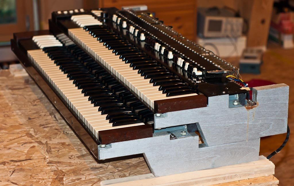
9.1 Nine contacts per key & key click
The theory of the key-contact matrix is fully developed in Vol 02 §“The key-contact matrix & busbars” — what follows is the physical and service description needed at the bench.
Pressing a key on the B-3 or C-3 closes nine separate contact pairs simultaneously, one per drawbar footage, in a single wiping action. Each contact pair consists of a flexible spring arm attached to the key’s undercarriage and a busbar rod running the full length of the manual. The spring arm’s tip is palladium; the busbar is a steel rod with a palladium wire spot-welded along its length (HammondWiki, “Bus Bar,” dairiki.org; HammondWiki, “BusbarLubeJob,” dairiki.org). The palladium-to-palladium wipe is the electrical contact: the spring arm’s palladium tip wipes across the busbar’s palladium wire as the key travels, making and breaking an audio-level connection for that footage frequency.
Each manual has nine busbars — one per drawbar footage (16′, 5⅓′, 8′, 4′, 2⅔′, 2′, 1⅗′, 1⅓′, 1′) — each carrying the tonewheel-derived signal for every key position in that footage (HammondWiki, “Bus Bar,” dairiki.org; Hammond B-3/C-3 Service Manual). With 61 keys per manual and 9 contacts per key, each manual accounts for 549 key-contact points; across both manuals and the 25-note pedalboard the full console total is approximately 1,220 switch contacts (electricdruid.net, “Technical aspects of the Hammond Organ”; Vol 02 §“The key-contact matrix & busbars”). Every contact carries a live audio-level AC signal during play, which makes contact cleanliness a direct audio-quality concern rather than a reliability-only concern.
Note: The B-3/C-3 and A-100 use the palladium-wire-on-steel-rod busbar construction. Some later Hammond models (certain M-series and spinet consoles) use round gold-plated rods or square rods, which lack the spot-welded palladium wire and respond somewhat differently to cleaning. The service procedures in this volume are written for the B-3/C-3 palladium-wire type; do not assume they apply identically to gold-plated-rod models without confirming the construction present (BusbarLubeJob, dairiki.org).
Warn: Do not file, sand, or abrade the palladium wire on the busbar or the palladium-tipped spring arm. See §“The Hammond fix” for safe cleaning — abrasion permanently destroys the contact and replacement is the only remedy.
9.1.1 Key-click: the service angle
The key click is a direct consequence of how the nine contacts close and open. The nine spring arms do not all make or break contact at exactly the same instant — each arm has slightly different spring tension, travel, and wipe geometry, and contact bounce occurs on each arm independently. Switching nine live audio-frequency AC signals through imperfect, non-simultaneous contacts produces a brief broadband transient at note-on and note-off: the key click (electricdruid.net; Vol 02 §“The key-contact matrix & busbars”). This transient is an artifact of the switching mechanism, not a designed waveform, but it is intrinsic to the B-3’s attack characteristic and is a defining part of the sound.
The service implication: over-cleaning, repositioning, or mechanically altering the contact geometry changes the click character, even if it resolves the oxidation problem. The goal of the Hammond fix is to restore the factory wipe — not to improve on it. The palladium-to-palladium wipe geometry engineered into the instrument is correct; cleaning and lubrication are the only interventions needed.
9.2 Diagnosing weak/missing harmonics
Because each key has an independent spring arm for each of its nine footages, the symptom pattern directly identifies the fault level:
Table 1 — symptom pattern directly identifies the fault level
| Symptom | Pattern | Probable cause |
|---|---|---|
| One drawbar missing or faint on one specific key | Dead on one footage, one key only | Oxidized contact spring for that footage on that key |
| Crackle or intermittent level — one key, one drawbar | Works sometimes; fails under other strokes | Early-stage oxidation, light enough to clear with exercise |
| One drawbar weak or silent on all keys | All keys affected at the same footage | Busbar oxidation or contamination for that footage; busbar shift needed |
| Multiple drawbars missing on one key | Several footages dead for the same key | Severely dirty contacts; full busbar service likely needed |
| Percussion absent; K terminal reads 0 VDC with no key depressed | Percussion does not fire; K terminal grounded | Zinc-dendrite short on the 1′ busbar — see Vol 08 §“Percussion failure modes” before touching the contacts |
| All notes dead on one or both manuals | No output across any drawbar position | Not a contact fault — begin triage from Vol 07 (generator), Vol 08 (AO-28), or Vol 11 (Leslie) |
Isolation sequence:
- Pull each drawbar individually and play the suspect key to identify which footage is affected. If pulling one specific drawbar to position 0 changes the symptom: that footage’s busbar or that key’s spring arm for that footage is the suspect.
- Test the same footage on adjacent keys. If all keys are equally affected in the same footage: the busbar itself is oxidized, and a busbar shift (§“The Hammond fix, Step 2”) is the first move. If only a few keys are affected: the spring arms on those keys are oxidized, and key exercise (§“Step 1”) clears most cases.
- For percussion or K-terminal symptoms: diagnose the percussion circuit in Vol 08 §“Percussion failure modes” before any busbar intervention — the zinc-dendrite short that kills percussion sits on the 1′ busbar circuit and requires the specific zap-clean procedure described there, not ordinary busbar cleaning.
- Before attributing a persistent dead harmonic to the contacts alone, rule out a tonewheel generator shunt-capacitor failure for that frequency (Vol 07 §“Dead-note triage”) and a matching-transformer secondary-tap failure (Vol 08 §“The matching transformer”). The triage sequence exhausts lower-invasiveness causes before committing to a busbar clean.
Note: Each contact carries a live audio-level signal with no signal redundancy — a single oxidized contact mutes exactly one harmonic of exactly one note (Vol 02). This precision makes the symptom a reliable diagnostic indicator. Trust it: if pulling the 2⅔′ drawbar on key C4 reveals silence, it is the 2⅔′ spring arm on that key.
Warn: Do not apply the busbar-shift or full busbar-clean procedure to a percussion / K-terminal fault (missing percussion, K terminal at 0 VDC). A zinc-dendrite short on the 1′ busbar requires the specific procedure in Vol 08 §“Percussion failure modes” — ordinary busbar cleaning will not clear it and may obscure the fault.
9.3 The Hammond fix
The graduated three-step cleaning procedure for dirty or oxidized key contacts. Always work least-invasive first; most problems resolve at Step 1 or Step 2 without any disassembly.
Pre-procedure requirements checklist:
Table 2 — Pre-procedure requirements checklist:
| Item | Notes |
|---|---|
| Console unplugged; AO-28 B+ discharged and confirmed at 0 VDC | Prerequisite for any console underside access — Vol 06 §“Capacitor-discharge procedure” |
| All preset keys cancelled | Press the Cancel key (labelled “C” in the preset row) to release any latched preset; a latched preset during busbar work risks contact damage |
| Isopropyl alcohol, ≥ 90% | Safe contact cleaner for Step 3 busbar clean |
| Nevr-Dull metal polish wadding | Step 3 initial rod clean — steel rod body only; see handling notes in Step 3 |
| Hammond busbar lubricant (or Tunerlub / GC conductive grease as substitute) | Applied after cleaning in Step 3 (BusbarLubeJob, dairiki.org) |
| Posterboard or newspaper sheets | Protects organ finish during manual removal |
| Folded matchbook or thin cardboard spacer | Blocks the Cancel key against accidental preset latch during Step 3 |
Warn: Do not use metal files, sandpaper, emery cloth, Scotch-Brite, pencil erasers, or any abrasive tool directly on the palladium contact wires or the palladium-tipped spring arms. The palladium wire on each busbar is fine-gauge precious metal, spot-welded to the steel rod at intervals; abrading it removes the contact material permanently and reduces the wire diameter until the spot-weld zones fail. A busbar whose palladium wire has been filed or sanded cannot be restored — replacement is the only remedy (BusbarLubeJob, dairiki.org; lambertsmusicsolutions.com). Do not use WD-40, silicone spray, petroleum-based lubricants, or residue-leaving aerosol cleaners in the contact area; these attract dust and gum the contact surfaces over time.
9.3.1 Step 1 — Exercise the keys
With the console running normally, strike the affected key firmly approximately 20 times in rapid succession — harder than normal playing force (b3world.com; dairiki.org, “How To Clean Key Contacts”). The wiping action between the palladium spring-arm tip and the palladium busbar wire dislodges light surface oxidation and dust. Cancel all preset keys before beginning (press the Cancel key to release any latched preset) so the exercise runs against the playing drawbars, not a preset voice.
Most intermittent contacts at early-stage oxidation clear at Step 1. After exercise, verify the note across all nine drawbars individually before declaring the problem resolved.
9.3.2 Step 2 — Shift the busbar
If Step 1 fails, the busbar shifter moves every spring arm on that manual to a fresh, un-oxidised section of the busbar wire, simultaneously displacing accumulated dust from all contact points (dairiki.org, “How To Clean Key Contacts”).
The busbar shifter on the B-3/C-3 is a slotted shaft, approximately ½ in (12.7 mm) in diameter, protruding from the rear of the manual chassis. Rotate it approximately two turns in either direction (dairiki.org). Perform this with the console powered off and unplugged and all keys released.
Warn: Do not operate the busbar shifter with keys held down by a board, weight, or tool unless the condition of every spring arm and busbar wire has been positively confirmed as undamaged. A worn or cracked spring arm can be sheared by the busbar moving against it under load (dairiki.org). Standard procedure: all keys released, console unplugged, all presets cancelled — then shift.
After shifting, power the console and verify all notes across all nine drawbars and all 61 keys. If the problem clears, the instrument may be returned to service; no further busbar work is needed.
9.3.3 Step 3 — Full busbar clean (last resort)
If Steps 1 and 2 fail, the busbars must be removed from the manual chassis and cleaned individually. This is a multi-hour disassembly procedure (lambertsmusicsolutions.com; BusbarLubeJob, dairiki.org). It requires manual removal (§“Removing & reseating a manual” below) and individual busbar extraction. This work is best performed by an experienced technician; incorrect handling permanently destroys busbars.
- Unplug the console. Discharge and confirm 0 VDC at the AO-28 B+ rail per Vol 06 §“Capacitor-discharge procedure.” Keep the console unplugged throughout.
- Block the Cancel key. Wedge a folded matchbook or thin cardboard under the Cancel key so no preset can accidentally latch during the procedure (BusbarLubeJob, dairiki.org).
- Protect the console finish. Lay posterboard or several layers of newspaper across the top of the console and at both cheek-block ends (BusbarLubeJob, dairiki.org).
- Remove the manual chassis per §“Removing & reseating a manual” below.
- Extract each busbar individually. Busbars slide out of their guide channels along the length of the manual. Handle each by the steel rod body only — do not press, grip, or contact the palladium wire with bare skin; skin oils contaminate the contact surface (BusbarLubeJob, dairiki.org). If a busbar meets resistance, stop and inspect for a bend or obstruction — do not force it (BusbarLubeJob, dairiki.org). Kinking the rod or displacing the palladium wire is a permanent defect requiring busbar replacement (lambertsmusicsolutions.com).
- Initial clean: Nevr-Dull wadding. Wipe the steel rod body with Nevr-Dull metal polish wadding to remove surface oxidation and contamination, using light even strokes along the rod (BusbarLubeJob, dairiki.org). If the wadding catches, tears, or snags at any point, stop immediately and inspect the palladium wire at that location for broken or missing segments between spot welds — a broken palladium wire means the busbar is beyond cleaning and must be replaced (BusbarLubeJob, dairiki.org).
- Alcohol wipe. After the Nevr-Dull pass, wipe the rod with isopropyl alcohol (≥ 90%) on a clean cloth or prep pad — one pad per rod — to remove all polish residue from the steel body and the palladium wire (BusbarLubeJob, dairiki.org). Allow to dry completely before applying lubricant.
- Apply busbar lubricant. Apply a thin, even coat of Hammond busbar lubricant to the cleaned rod and wire surface. Tunerlub (GC Electronics conductive grease) is the accepted substitute when Hammond busbar lubricant is unavailable (BusbarLubeJob, dairiki.org). The lubricant reduces friction and wear between the spring arm and the busbar wire over decades of use. Do not over-apply; excess lubricant migrates to adjacent contact surfaces and attracts dust.
- Reinstall the busbar. Slide the cleaned, lubricated busbar back into its guide channel, handling it by the rod body only. Confirm full seating and correct channel alignment before moving to the next busbar.
- Repeat for all nine busbars of the manual, one at a time.
- Reinstall the manual chassis per §“Removing & reseating a manual.”
- Test the full keyboard — all 61 keys, all nine drawbars — before closing the console.
9.4 Drawbar contact service
The nine drawbars per manual are multi-position sliding contacts. Each drawbar slides through nine positions (0 = off … 8 = full), selecting a different level tap from the matching transformer secondary at each position, with each increment of one position adding approximately 3 dB of output for that footage (Vol 02 §“Additive synthesis & the drawbars”; dairiki.org, “Drawbars”). The two adjustable preset keys — A♯ and B on each manual, the “Adjust” presets — store a complete set of drawbar positions for both manuals (Vol 03 §“Preset keys”; Hammond B-3/C-3 Service Manual); their contact assemblies are identical in construction to the playing drawbars and subject to the same oxidation and cleaning requirements.
9.4.1 Drawbar contact assembly
Each drawbar assembly contains a sliding contact arm that rides along a nichrome resistance wire (rated at 1 Ω per the B-3/C-3 service data; dairiki.org, “How To Clean Drawbar Contacts”). This resistance wire provides the physical wiper surface for the nine tap positions; the actual level steps derive from the matching transformer secondary taps (Vol 02 §“Additive synthesis & the drawbars”). As the drawbar is pulled toward position 8, the sliding arm connects to taps presenting progressively lower source attenuation, adding approximately 3 dB per step (Vol 02).
The B-3/C-3 has 9 playing drawbars per manual — 18 playing drawbars total across both manuals. The two adjustable preset keys (A♯ and B, the “Adjust” presets) each store a full set of drawbar positions for the complete console; refer to Vol 03 §“Preset keys” for the preset-key geometry and the number of stored positions across both manuals. The drawbar contact assemblies serving the adjustable presets are identical in construction and cleaning requirements to the playing drawbars.
9.4.2 Symptom table
Table 3 — Symptom table
| Symptom | Probable cause | Fix |
|---|---|---|
| Scratchy or stepped level as drawbar moves | Oxidized contact arm or contaminated resistance wire | Work drawbar through full travel; apply residue-free contact cleaner |
| One level position dead or silent | Oxidized or open tap at that position | Contact cleaner; burnishing tool; inspect nichrome wire at that tap |
| No output at any position | Nichrome wire broken or contact arm open | Inspect wire; replace with ⅛ W, 1 Ω resistor if broken — do not solder nichrome |
| Drawbar crackles at rest | Loose contact arm or corroded tap junction | Contact cleaner; inspect contact arm seating |
| Scratchy or missing adjustable preset voice | Oxidized contacts in the A♯ or B preset contact assembly | Contact cleaner applied to the preset contact area per the same procedure |
9.4.3 Cleaning procedure
Warn: Use only contact cleaners formulated as safe for precious-metal contacts in the drawbar assembly. A residue-heavy aerosol or a cleaner not rated for precious-metal contacts can leave a contaminating film and displace the factory lubricant. Do not use WD-40, silicone spray, or general-purpose aerosol lubricants in the drawbar area.
Tools required: residue-free contact cleaner (DeoxIT, Contact Clean, or PreservIT — the latter two are the current equivalents of the discontinued Cramolin R-5 and Cramolin Blue; dairiki.org, “How To Clean Drawbar Contacts”); aerosol extension tube; optional contact-burnishing tool; isopropyl alcohol (≥ 90%).
Prerequisites: console unplugged.
- Pull all drawbars to the full-on position (position 8). This exposes the maximum contact surface inside the assembly.
- Spray contact cleaner from the rear of the console. Using the aerosol extension tube, direct a short burst of cleaner (DeoxIT or equivalent) into the back of each drawbar assembly — enough to wet the contact area without flooding it (dairiki.org, “How To Clean Drawbar Contacts”).
- Work each drawbar through its full travel immediately after spraying. Slide from position 0 to position 8 and back, five to ten times, to distribute the cleaner across the nichrome wire and all tap contacts (dairiki.org).
- Allow the cleaner to dry. Residue-free contact cleaners flash off rapidly (est., approximately 1 minute; verify with the specific product datasheet); allow complete drying before applying power.
- Test. Power the console and verify smooth, continuous level change across all nine positions of each drawbar — no crackle, stuck steps, or dropouts.
- Burnishing (stubborn contacts only). For contacts that do not respond to cleaner alone, a contact-burnishing tool may be applied to the contact arm surface — the tool is designed for this task (minimal material removal, removes oxide). A metal file or sandpaper is never appropriate here (dairiki.org).
9.5 Removing & reseating a manual
Manual removal is required for a full busbar lube job (§“The Hammond fix, Step 3”), contact spring replacement, or wiring repair at the harness level. The B-3/C-3 manual chassis is heavy and requires two people for safe handling (BusbarLubeJob, dairiki.org). The wiring harness that connects the manual to the console — carrying tonewheel audio signals and the foldback circuit connections — is the primary care point: incorrect reconnection produces wrong pitches or a dead section of the keyboard.
Tools: posterboard or newspaper for finish protection; Phillips and flat-blade screwdrivers (medium); non-conductive cable labels or masking tape with marker; camera or phone (for wiring photographs before disconnection).
Prerequisites: console unplugged; AO-28 B+ discharged and confirmed at 0 VDC per Vol 06 §“Capacitor-discharge procedure.”
Warn: The manual wiring harness carries audio-level AC signals from the tonewheel generator — not mains or high voltage. The console must still be unplugged during manual removal because the harness runs physically adjacent to the AO-28 chassis (Vol 08) and the start/run motor area (Vol 07), both of which carry hazardous potentials. Do not remove a manual with the console plugged in.
9.5.1 Removal
- Unplug the console. Discharge and confirm 0 VDC at the AO-28 B+ rail per Vol 06 §“Capacitor-discharge procedure.” Keep the console unplugged throughout the procedure.
- Photograph the wiring harness in detail before disconnecting anything. Photograph the connector body, individual lead colours and their destinations, and any wires that loop or cross. Label any connector that could be seated in more than one orientation with a masking-tape flag before unplugging it.
- Protect the console finish. Lay posterboard or several layers of newspaper across the top of the console and at both cheek-block ends where the manual chassis will be handled (BusbarLubeJob, dairiki.org).
- Block the Cancel key. Wedge a folded matchbook or thin cardboard under the Cancel key so that no preset can latch accidentally while the keyboard is being handled (BusbarLubeJob, dairiki.org).
- Disconnect the wiring harness. The harness typically connects at a multi-pin connector at the rear or underside of the keyboard frame — disconnect it gently, without twisting or pulling the wires. On some B-3/C-3 production variants, certain foldback-circuit wires are soldered directly to busbar terminals rather than routed through a connector; if soldered connections are present, photograph and label each lead individually before applying heat, and record which wire attaches to which busbar terminal (BusbarLubeJob, dairiki.org; Hammond B-3/C-3 Service Manual).
- Unseat the manual chassis with two people. The chassis slides or lifts out of its retaining channels in the console frame. With one person at each end, lift evenly — do not allow one end to advance ahead of the other, which binds the busbar guide channels and risks kinking the busbars (BusbarLubeJob, dairiki.org). The upper-manual chassis weight is not stated in the service manual (est., approximately 15 lb to 20 lb / 6.8 kg to 9.1 kg); use two people regardless of apparent weight.
- Rest the manual face-up on a padded workbench. Do not stack anything on top of it.
9.5.2 Reinstallation
- Verify wiring labels against the photographs taken at removal Step 2.
- Seat the manual chassis into the console frame with two people, guiding both ends into the retaining channels simultaneously. The chassis should enter smoothly; any binding indicates misalignment — back out and re-align before applying any additional force.
- Reconnect the wiring harness. Match each connector and lead to the photographed positions. If foldback wires were desoldered, resolder each lead to the correct busbar terminal — confirmed against the photographs and the Hammond B-3/C-3 Service Manual schematic. Verify polarity and routing before soldering.
- Test the full keyboard before closing the console. With all drawbars at a consistent position (all at 8, for example), play chromatically across all 61 keys on each manual and verify that every note is present, at the correct pitch, and consistent across all nine drawbars. Pay particular attention to the bottom octave (heaviest foldback wiring for the 16′ and 5⅓′ footages) and the top octave (upper-harmonic foldback boundaries; Vol 02 §“Foldback”).
Warn: Foldback wiring must be reconnected to the correct busbar terminals. The B-3/C-3 foldback circuit routes specific tonewheel signals to key contacts at the extremes of the manual: the lowest-octave 16′ and 5⅓′ contacts reuse higher-frequency tonewheels rather than sub-audio wheels that do not exist, and the upper-harmonic footages at the top octave reuse the highest available wheels rather than demanding non-existent ones (Vol 02 §“Foldback”). An incorrectly reconnected foldback wire places the wrong tonewheel signal on those keys, producing wrong pitches, missing notes, or an octave error at the keyboard extremes. Always play the full chromatic range after reinstallation and confirm pitch at both extremes before returning the instrument to service.
Sources consulted: Hammond B-3/C-3 Service Manual (key contact arrangement, drawbar tap mechanism, wiring harness, foldback circuit, adjustable preset keys A♯/B); HammondWiki, “Bus Bar” (dairiki.org) — nine busbars per manual confirmed, palladium wire spot-welded to steel rod, palladium-tipped contact spring arms, maintenance overview, gold-plated-rod vs palladium-wire type distinction; HammondWiki, “How To Clean Key Contacts” (dairiki.org) — three-step exercise / shift / clean procedure, busbar shifter at approximately ½ in (12.7 mm) diameter shaft, approximately 20 key strikes, approximately 2 turns, depressed-key warning; HammondWiki, “BusbarLubeJob” (dairiki.org) — Nevr-Dull + isopropyl alcohol prep pad + Hammond busbar lubricant procedure, matchbook Cancel-key block, posterboard finish protection, two-person lift requirement, “don’t force” warning, palladium wire catch-and-tear inspection criterion, Tunerlub as lubricant substitute, gold-plated-rod vs palladium-wire type note; HammondWiki, “How To Clean Drawbar Contacts” (dairiki.org) — nichrome 1 Ω resistance wire confirmed, DeoxIT / Contact Cleaner / PreservIT from rear with aerosol extension tube, full travel cycle five to ten times, ⅛ W 1 Ω resistor substitute for broken nichrome confirmed, contact-burnishing tool note; b3world.com, “Hammond Maintenance” — ~20-key-strike method confirmed; Lambert’s Music Solutions, “Hammond Organ B3 Mark 1 Busbar Cleaning” (lambertsmusicsolutions.com) — professional-level caution, multi-hour duration, full manual removal required, kink and bare-hand damage warning; electricdruid.net, “Technical aspects of the Hammond Organ” — approximately 1,220 total console switch contacts, nine contacts per key confirmed. Estimates explicitly flagged: manual chassis weight (approximately 15–20 lb / 6.8–9.1 kg) not stated in the service manual, marked (est.); contact-cleaner dry time (approximately 1 minute) from product-class general data, marked (est.); position-level figures (approximately −21 dB at position 1) derived from the approximately 3 dB/step relationship in Vol 02 and marked (est.). Palladium wire as contact material on both the busbar rod and the key contact spring: VERIFIED from HammondWiki Bus Bar + BusbarLubeJob + organforum.com busbar-metal thread. Safe cleaner for busbar (isopropyl ≥ 90% / Nevr-Dull for steel rod body): VERIFIED from BusbarLubeJob (dairiki.org). Nichrome resistance wire at 1 Ω: VERIFIED from dairiki.org “How To Clean Drawbar Contacts.” Cross-references: Vol 02 §“The key-contact matrix & busbars” (contact theory, key-click origin, nine contacts per key, foldback wiring, approximately 1,220 contacts, audio-level signal), §“Additive synthesis & the drawbars” (matching transformer tap mechanism, approximately 3 dB per step); Vol 03 §“Preset keys” (adjustable preset geometry, A♯/B preset keys, drawbar positions stored per preset); Vol 06 §“Safety first: the death cap & B+” and §“Capacitor-discharge procedure” (AO-28 B+ discharge prerequisite for all underside work); Vol 07 §“Dead-note triage” (rule out generator fault before busbar work); Vol 08 §“Percussion failure modes” (K-terminal and zinc-dendrite short on 1′ busbar), §“Power supply” (AO-28 approximately +200 VDC hazard), §“The matching transformer” (triage before busbar work); Vol 10 §“The vibrato/chorus scanner” (adjacent scanner service; scanner sits near the manual area); Vol 18 (drawbar table, service-specification reference, source bibliography).
Comments (0)