Hammond B-3 · Volume 18
Hammond B-3 — Vol 18: Reference & Cheatsheet
This volume consolidates the values established across Vols 01–17 into a single bench
reference: a model-comparison table, generator and motor specs, weight and dimension data, a
drawbar footage listing, a registration chart with preset key registrations, a drawbar
footage-to-harmonic table, a tonewheel frequency reference, service specification tables for
the AO-28 preamplifier and Leslie 122 amplifier, vibrato and percussion control reference
tables, a chop-build planning reference with weight-budget and preamp comparison tables, a
consolidated tool and consumable list, and a de-duplicated bibliography of every source cited
across the series. This volume introduces no new measurements; every value here traces to the
volume that first established it, cited in each table row as “(Vol N).” Values already flagged
(est.) or (not published) in their origin volume are repeated with the same flag rather
than hardened into specifications. Where two volumes appeared to state a value differently, the
apparent difference is reconciled inline with a > **Note:**.
Note: Drawbar registrations are written in the conventional nine-digit form grouped
88 8888 888, read left to right as the physical bar order 16′ 5⅓′ 8′ 4′ 2⅔′ 2′ 1⅗′ 1⅓′ 1′ (Vol 03 §“The drawbars”). Do not use this volume as the sole reference for any service procedure — follow the full procedure in the appropriate service volume.
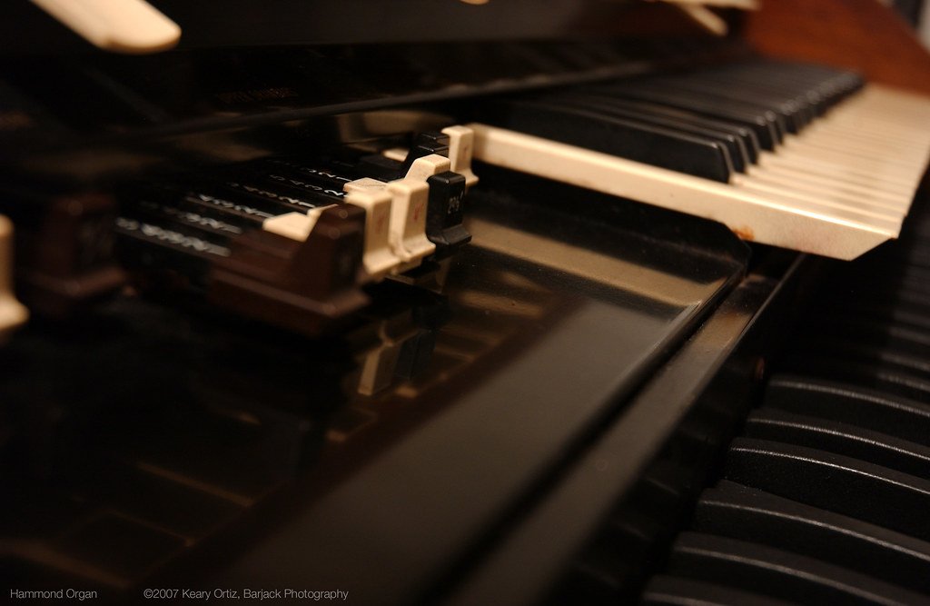
18.1 Specs at a glance
18.1.1 B-3, C-3 and A-100 model comparison
All three models share an electrically identical signal chain: the same 91-active-tonewheel generator, the same AO-28 eight-tube preamplifier, the same nine-drawbar-per-manual complement, the same key-contact matrix, and the same vibrato scanner. Tonal differences among the three trace to cabinet acoustics and the presence or absence of internal amplification — not to the generator or preamp (Vol 01 §“Lineage & the tonewheel console family”; Vol 13 §“What ‘chopping’ means”).
Table 1 — B-3, C-3 and A-100 model comparison
| Feature | B-3 | C-3 | A-100 |
|---|---|---|---|
| Production span | 1954–1975 | 1954–1975 | 1959–1975 |
| Primary market | Stage / studio | Church / studio | Home |
| Cabinet style | Console on four separate turned spindle legs + leg stretcher | Console on leg-panel enclosures; toe-piston rail | Console with built-in speaker grille panels |
| Internal speakers | None | None | Yes — built-in power amplifier and drivers |
| Built-in reverb | No | No | Yes (on most production) |
| External Leslie output | 6-pin Amphenol 6H balanced | 6-pin Amphenol 6H balanced | 6-pin Amphenol 6H balanced |
| Tonewheel generator | 91 active / 96 total — identical | 91 active / 96 total — identical | 91 active / 96 total — identical |
| AO-28 preamp | 8 tubes — identical | 8 tubes — identical | 8 tubes — identical |
| Drawbar complement | 9 upper + 9 lower + 2 pedal | 9 upper + 9 lower + 2 pedal | 9 upper + 9 lower + 2 pedal |
| Harmonic Percussion | Yes | Yes | Yes |
| Vibrato / chorus scanner | Yes | Yes | Yes |
| Chop suitability | Grade A/B: restore; Grade D / derelict: chop candidate | Grade A/B: restore; Grade D / derelict: chop candidate | Natural chop donor — built-in speakers removed regardless (Vol 13 §“The ethic”) |
Sources: Vol 01 §“Lineage & the tonewheel console family”; Vol 13 §“The ethic: what to chop, what to spare”; en.wikipedia.org (“Hammond organ”); Hammond B-3/C-3 Service Manual.
Note: The C-3’s toe-piston rail and leg-panel enclosure are structural, not electronic, differences from the B-3. A C-3 and B-3 of the same production year are tonally indistinguishable (Vol 01).
Dating a console (Vol 01 §“Spotting a genuine console”):
Table 2 — Dating a console (Vol 01 §"Spotting a genuine console")
| Method | Detail |
|---|---|
| Serial-number prefix | A ≈ 1969, B ≈ 1970, C ≈ 1971, D ≈ 1972, E ≈ 1973 |
| Data-plate location | Inside the console cabinet; records model, serial, and date |
| AO-28 power transformer | Silver = early production; black = later production |
| EIA date codes | Ink-stamped on capacitors and resistors inside the chassis — two-digit year / week |
18.1.2 Generator and motor
Table 3 — Generator and motor
| Parameter | Value | Source |
|---|---|---|
| Tonewheels total | 96 (24 shaft assemblies × 2 wheels × 2 groups = 24 × 2 × 2) | Vol 02 §“Wheels, gears, and grouping”; dairiki.org Tone Generator |
| Tonewheels — active sound sources | 91 (5 blank balance wheels) | Vol 01; Vol 02; dairiki.org Tone Generator |
| Blank balance wheels | 5 | Vol 02 §“Wheels, gears, and grouping” |
| Shaft assemblies | 48 (24 gear ratios × 2 shafts) | Vol 07 §“The capillary oiling system”; bentonelectronics.com |
| Tuning reference | A = 440.0 Hz exactly; all other pitches are integer-gear approximations (≤ 0.69 cent error in first 7 octaves; ≤ 1.93 cent at 192-tooth top-octave cap) | Vol 02 §“Frequency derivation”; dairiki.org GearRatio |
| Lowest tonewheel (pedal low C) | ≈ 32.7 Hz | Vol 05 §“Pedal tone generation”; electricdruid.net |
| Highest tonewheel | Approximately 5 920 Hz (F#7) — the highest wheels run above the 1 200 rpm base shaft via the generator gear train; naive 192 × 20 = 3 840 Hz omits the gear ratio (Vol 02; Vol 07) | Vol 02 §“Frequency derivation”; dairiki.org GearRatio; Vol 07 §“Tonewheel construction” |
| Key contacts | 9 per key, one per footage; ~1 220 total console switch contacts | Vol 02 §“The key-contact matrix” |
| Run motor type | Non-self-starting synchronous | Vol 02 §“The synchronous motor”; Hammond B-3/C-3 Service Manual |
| Run motor speed — 60 Hz mains | 1 200 rpm | Vol 02; Vol 07; bentonelectronics.com |
| Run motor speed — 50 Hz mains | 1 500 rpm | Vol 02; Vol 07; bentonelectronics.com |
| Run motor — each field coil | ≈ 180 Ω | Vol 02; Vol 07; bentonelectronics.com; dairiki.org |
| Run motor — both coils in parallel | ≈ 90 Ω | Vol 02; Vol 07; bentonelectronics.com |
| Start motor type | Shaded-pole induction; spring-return pinion clutch | Vol 07 §“Start & run motors”; bentonelectronics.com |
| Start-sequence hold time | ≈ 8 s (est.) | Vol 02; Vol 03; bentonelectronics.com |
| Start motor series resistor | 250 Ω / 10 W (single-generator console); 125 Ω (dual-generator models) | Vol 15 §“The original Hammond start/run circuit”; bentonelectronics.com |
| AO-28 output (GG terminals) | ≈ 3–4 V AC RMS balanced (≈ +12 to +14 dBu, est.) | Vol 02; Vol 04; Vol 08; bentonelectronics.com |
| AO-28 B+ rail | ≈ +200 VDC (at V-7 pin 1); persists on filter caps after power-off | Vol 08 §“Power supply & safe discharge”; bentonelectronics.com |
18.1.3 Console and Leslie weights and dimensions
All weights (est.) from dairiki.org WhatDoesAHammondWeigh and community measurement; no factory sub-assembly weight specification has been located in the service literature (Vol 13).
Table 4 — Console and Leslie weights and dimensions
| Item | Weight (est.) | Dimensions | Source |
|---|---|---|---|
| Console body alone | ≈ 310 lb (141 kg) | ≈ 48½ in W × 38¼ in H × 24–25 in D (1 232 mm × 972 mm × 610–635 mm) | Vol 06; Vol 13; dairiki.org WhatDoesAHammondWeigh; b3sforsale.com |
| Full rig (console + bench + pedalboard, packed) | ≈ 425 lb (193 kg) | — | Vol 06; Vol 13; dairiki.org WhatDoesAHammondWeigh |
| Leslie 122 cabinet | ≈ 145–150 lb (66–68 kg) | 41 in (1 041 mm) H; footprint ≈ 19 × 23 in (est.) | Vol 06; Vol 13; hammondorganco.com |
| Tonewheel generator (extracted) | ≈ 45 lb (20 kg) | — | Vol 07; Vol 13; dairiki.org WhatDoesAHammondWeigh |
| Each manual assembly | ≈ 48 lb (22 kg) | — | Vol 13; dairiki.org WhatDoesAHammondWeigh |
| AO-28 preamp chassis | ≈ 15 lb (7 kg) | ≈ 18–22 in × 7–9 in (457–559 mm × 178–229 mm) + 3.5 in (89 mm) tube clearance (est.) | Vol 13; Vol 15; dairiki.org WhatDoesAHammondWeigh |
| 25-note pedalboard | ≈ 75 lb (34 kg) | — | Vol 05; Vol 13; dairiki.org WhatDoesAHammondWeigh |
18.1.4 Drawbar footage listing
Nine drawbars per manual; two pedal drawbars (16′ + 8′ only). Positions 0 (off) through 8 (full); each step ≈ 3 dB (Vol 02). Brown drawbars first two positions; white and black as listed below (Vol 02 §“Additive synthesis”; Vol 03 §“The drawbars”).
Table 5 — Drawbar footage listing
| Position | Footage | Colour |
|---|---|---|
| 1 | 16′ | Brown |
| 2 | 5⅓′ | Brown |
| 3 | 8′ | White |
| 4 | 4′ | White |
| 5 | 2⅔′ | Black |
| 6 | 2′ | White |
| 7 | 1⅗′ | Black |
| 8 | 1⅓′ | Black |
| 9 | 1′ | White |
18.2 Registration chart
Drawbar positions in the format 88 8888 888 (16′ 5⅓′ 8′ 4′ 2⅔′ 2′ 1⅗′ 1⅓′ 1′). Named
voicings are widely published starting points; players vary freely. Sources: Hammond B-3
Owner’s Playing Manual; hammondwiki.org StandardPresets; Vol 03 §“Driving it” and §“Preset keys.”
Table 6 — Registration chart
| Name / use | Registration | Description |
|---|---|---|
| Full organ | 88 8888 888 | All nine drawbars at maximum — full, dense stack (Vol 02 §“Additive synthesis”) |
| Classic jazz — Jimmy Smith (comp) | 88 8000 000 | 16′ + 5⅓′ + 8′ — fat, fundamental-heavy with quint body (Vol 03 §“Driving it”) |
| Jimmy Smith (lead / solo) | 88 8800 000 | Adds 4′ for cut on a single-line solo |
| Blues / rock | 88 8000 008 | Smith-style base plus 1′ for sparkle / edge into a driven Leslie |
| Bright flutes | 00 8888 000 | Upper-octave cluster (Vol 03 §“Driving it”, Tip) |
| Soft flute (8′ + 4′) | 00 8400 000 | Mellow two-footage flute; cf. the F-key preset 00 5403 000 (Vol 03) |
| String (Salicional) | 00 4544 222 | Thin, reedy string voice — identical to the E-key Salicional preset (Vol 03) |
| Gospel pad | 88 8800 008 | Wide body plus 1′ shimmer for swelling sustained chords |
| Theatre / tibia | 80 8808 008 | Full tibia flute (16′ 8′ 4′ 2′ 1′) for theatre or gospel |
18.2.1 Upper-manual preset key registrations
Preset keys are the reverse-colour keys at the top of the upper keyboard (Vol 03 §“Preset keys”). A♯ and B are the two Adjust (live drawbar) positions; B is the only preset that enables Harmonic Percussion.
Table 7 — Upper-manual preset key registrations
| Preset key | Registration | Notes |
|---|---|---|
| C | Cancel | All-cancel — manual silent |
| C♯ | 00 5320 000 | — |
| D | 00 4432 000 | — |
| D♯ | 00 8740 000 | — |
| E | 00 4544 222 | Salicional |
| F | 00 5403 000 | Flute |
| F♯ | 00 4675 300 | — |
| G | 00 5644 320 | — |
| G♯ | 00 6876 540 | — |
| A | 32 7645 222 | — |
| A♯ | Adjust left | Live drawbar set A; percussion not available |
| B | Adjust right | Live drawbar set B; percussion source — percussion operable only from this preset |
Sources: Vol 03 §“Preset keys”; Hammond B-3/C-3 Service Manual.
18.3 Frequency and footage table
18.3.1 Drawbar footage and harmonic reference
The harmonic number below is relative to the 16′ sub-fundamental (treating 16′ as the 1st harmonic of the series). The interval above the 8′ key pitch (unison) is the most practical way to hear the relationship (Vol 02 §“Additive synthesis”; electricdruid.net).
Table 8 — Drawbar footage and harmonic reference
| Position | Footage | Colour | Harmonic (re 16′) | Interval re 8′ key pitch | Organ stop name |
|---|---|---|---|---|---|
| 1 | 16′ | Brown | 1st | 1 octave below | Sub-bass / Bourdon |
| 2 | 5⅓′ | Brown | 3rd | Perfect fifth above (3rd harmonic of the 16′ sub-fundamental) | Quint |
| 3 | 8′ | White | 2nd | Unison | Principal / Flute |
| 4 | 4′ | White | 4th | 1 octave above | Octave |
| 5 | 2⅔′ | Black | 6th | Octave + perfect fifth above | Nazard |
| 6 | 2′ | White | 8th | 2 octaves above | Super-octave |
| 7 | 1⅗′ | Black | 10th | 2 octaves + major third above (17th) | Tierce |
| 8 | 1⅓′ | Black | 12th | 2 octaves + perfect fifth above (19th) | Larigot |
| 9 | 1′ | White | 16th | 3 octaves above | Piccolo |
Sources: Vol 02 §“Additive synthesis & the drawbars”; Vol 03 §“The drawbars”; electricdruid.net (Technical aspects of the Hammond Organ). The 5⅓′ quint sounds a perfect fifth above the 8′ unison (it is the 3rd harmonic of the 16′ sub-fundamental). The two brown drawbars (16′, 5⅓′) are termed ‘sub’ drawbars because they derive from the 16′ sub-octave, not because 5⅓′ sounds below the played key (see Vol 02 §‘Additive synthesis & the drawbars’).
18.3.2 Tonewheel frequency reference
At 1 200 rpm (60 Hz mains): frequency (Hz) = tooth count × 1 200 ÷ 60 = tooth count × 20. A = 440.0 Hz exactly; all other wheels are integer-gear approximations (Vol 02).
Table 9 — Tonewheel frequency reference
| Note | ET freq. (Hz) | Note | ET freq. (Hz) |
|---|---|---|---|
| C1 (pedal low C) | 32.70 | G1 | 49.00 |
| C♯1 | 34.65 | G♯1 | 51.91 |
| D1 | 36.71 | A1 | 55.000 |
| D♯1 | 38.89 | A♯1 | 58.27 |
| E1 | 41.20 | B1 | 61.74 |
| F1 | 43.65 | C2 | 65.41 |
| F♯1 | 46.25 | A4 (reference) | 440.000 |
Pedal frequencies C1–G2 are tabulated in full in Vol 05 §“Pedal tone generation.” The complete 91-tonewheel specification is at goodeveca.net (Hammond Tone Wheel Spec) and dairiki.org (GearRatio).
Note: Only A is exactly equal-tempered. Every other tonewheel sits a few cents off equal temperament by design — the source of the gentle “Hammond beats” (Vol 02 §“Tuning”). The actual low-C tonewheel measures ≈ 32.692 Hz, fractionally below the 32.70 Hz equal-tempered value tabulated above (Vol 02).
18.4 Service specs
18.4.1 Oiling schedule
Oil type (all generator and console motor points): Hammond tonewheel-generator oil — Hammond OG-1 or current equivalent; low-viscosity, non-detergent mineral oil. Never 3-in-1, detergent, multigrade automotive, or paraffin-containing oil — wrong oil cannot climb the cotton wicking threads, or gums them permanently (Vol 07 §“Why only Hammond oil”; bentonelectronics.com; hammondorganco.com/oils).
Table 10 — Oiling schedule
| Oiling point | Quantity | Interval | Source |
|---|---|---|---|
| Tone-generator funnels (×2, left and right) | Fill each funnel to full; allow to drain completely; repeat once — total: two fills per funnel. No mL figure specified in period documentation | Annually | bentonelectronics.com; Vol 07 §“Oiling procedure” |
| Motor / scanner felt tub (left-rear of console) | Moisten the felt only — do not flood; flooding migrates oil onto scanner plates and key contacts | Annually | bentonelectronics.com; Vol 07 |
| Upper oil cups — left (motor / scanner), if fitted | Half-full | Annually | Not present on all consoles; bentonelectronics.com; Vol 07 |
| Upper oil cups — right (generator), if fitted | To the top | Annually | Not present on all consoles; bentonelectronics.com; Vol 07 |
| Scanner shaft bearing | One very small drop (≈ 0.05–0.10 mL; est.) | When motor/scanner felt tub is serviced | bentonelectronics.com; Vol 07 |
| Leslie motor felt pads | Non-detergent sewing-machine oil acceptable for the Leslie felt pads (this tolerance does not extend to the console generator) | Annually | Vol 07; Vol 11 §“Motors, belts & oiling” |
Oil takes a week or more to reach every bearing after filling — do not judge oiling quality immediately after service (bentonelectronics.com; Vol 07).
18.4.2 AO-28 tube complement
Eight tubes in the AO-28 (B-3 / C-3 / A-100). Do not retube with a four-tube kit — the four-tube count confuses the AO-28 with the smaller AO-29 used in spinet models (Vol 08 §“Tube complement”; bentonelectronics.com).
Table 11 — AO-28 tube complement
| Designation | Type | Function | Failure symptom |
|---|---|---|---|
| V-1 | 6AU6A | Non-vibrato (direct) input preamp — first gain stage for the non-vibrato path | Silence or severe attenuation on the direct signal |
| V-2 | 6AU6A | Vibrato input preamp — first gain stage for the vibrato/chorus path | Silence or attenuation on the vibrato path |
| V-3 | 12BH7A | Output stage and vibrato drive | Weak or absent output across all drawbar settings |
| V-4 | 12AX7A | Volume / expression-pedal amplifier | Expression pedal without effect; output stuck at one level |
| V-5 | 6C4 | Percussion preamp — first amplification stage in the percussion chain | Percussion absent or very weak |
| V-6 | 6C4 | Percussion keyer — K-terminal swing: +25–30 VDC at rest → 0 VDC at key press | Percussion continuously on (V-6 shorted) or permanently off (V-6 open) |
| V-7 | 12AU7A | Voltage-controlled percussion decay amplifier; Fast/Slow decay set by capacitor | Wrong decay timing; no percussion attack envelope |
| V-8 | 6X4 | Rectifier — converts transformer secondary AC to ≈ +200 VDC B+ rail; most failure-prone of the eight | No B+ → silence from all stages |
Sources: bentonelectronics.com (“Servicing the Hammond B-3 Type Pre-Amp”); Hammond B-3/C-3 Service Manual; Vol 08 §“Tube complement.”
18.4.3 AO-28 filter capacitors
Primary power-supply filter capacitors (C56–C59). Replace at the original WVDC or higher; never fit an under-rated replacement into an HV rail (Vol 08 §“Filter-capacitor table”; Vol 06 §“Safety first”).
Table 12 — AO-28 filter capacitors
| Ref. | Original value | WVDC | Role | Replacement note |
|---|---|---|---|---|
| C56 | 40 µF | 450 V | First main B+ filter — highest voltage node after rectifier | Replace ≥ 450 WVDC; 47 µF acceptable |
| C57 | 40 µF | 400 V | Second B+ filter stage | Replace ≥ 400 WVDC; 47 µF acceptable |
| C58 | 30 µF | 350 V | Third filter section | Replace ≥ 350 WVDC; 33 µF acceptable |
| C59 | 10 µF | 350 V | Final filter / screen-supply bypass | Replace ≥ 350 WVDC; match value for screen stability |
| Multi-section can (alternative) | 40–40–30–10 µF | 450 V (first section) | Drop-in can replacement covering C56–C59 | bborgan.com and restoration suppliers; Vol 08 |
Sources: Hammond B-3/C-3 Service Manual; geocities.ws/x77dude/ao28.html (parts reference list); Vol 08 §“Filter-capacitor table.” B+ ≈ +200 VDC persists on filter caps after power-off — discharge through a ≥ 10 W resistor-limited tool and verify 0 VDC at every section before chassis work (Vol 06 §“Capacitor-discharge procedure”; Vol 08).
18.4.4 Leslie 122 tube and capacitor inventory
Table 13 — Leslie 122 tube and capacitor inventory
| Component | Type / value | Voltage rating | Notes |
|---|---|---|---|
| V1 | 12AU7A dual triode | Plates ≈ +130 VDC (est.) | V1a: balanced input amplifier and phase-splitter (drives 6550A grids); V1b: speed-switching detector via 1 MΩ to audio pair; cathode bias ≈ +25 VDC (Vol 04; Vol 11) |
| V2, V3 | 6550A matched pair | Plates ≈ +415 VDC | Push-pull Class AB output; always replace as a matched pair (bentonelectronics.com; Vol 11) |
| V4 | OC3 gas-discharge regulator | Drops ≈ 105 VDC → output ≈ +310 VDC | Pin 2 current-limiter: 470 Ω / 0.5 W resistor (bentonelectronics.com; Vol 11) |
| Rectifier | Silicon diode bridge | — | Solid-state on the great majority of production units; rectifier tube only on earliest examples (Vol 04; Vol 11) |
| Main filter can | 4-section: 30/30/30/10 µF @ 475 WVDC | 475 VDC per section | Original Mallory FP can. Replacement: CE Mfg C-EC30-30-30-10 (amplifiedparts.com; Vol 11) |
| Feedback / coupling cap | 0.0047 µF / 1 600 VDC film | 1 600 VDC | Between 12AU7A pin 3 and pin 5 via 390 kΩ; known DC leaker in the CDE “green” moulded family (bentonelectronics.com; Vol 11) |
| Driver-to-grid coupling caps | CDE “green” moulded film | Per unit schematic | Between 12AU7A driver output and each 6550A grid — widely reported failure population; check DC leakage before blaming tubes (bentonelectronics.com; Vol 11) |
| Shared cathode resistor | 150 Ω wirewound | — | Carries combined 6550A cathode current; wrong value (e.g., 125 Ω) overdrives tubes (organforum.com; Vol 11) |
Sources: bentonelectronics.com (“Servicing the Leslie 122 Amplifier”); Vol 04 §“The 40 W amplifier”; Vol 11 §“Amp recap & bias.”
18.4.5 Leslie 122 supply rails and bias
Table 14 — Leslie 122 supply rails and bias
| Supply node | Nominal voltage | Source |
|---|---|---|
| Rectifier output (reservoir section) | ≈ +430 VDC | bentonelectronics.com; Vol 04; Vol 11 |
| After filter choke | ≈ +420 VDC | bentonelectronics.com; Vol 04; Vol 11 |
| 6550A plates | ≈ +415 VDC | bentonelectronics.com; Vol 04; Vol 11 |
| OC3-regulated screen / driver rail | ≈ +310 VDC | bentonelectronics.com; Vol 04; Vol 11 |
| Preamp section (after 10 kΩ dropping resistor) | ≈ +260 VDC | bentonelectronics.com; Vol 04; Vol 11 |
| 12AU7A plates | ≈ +130 VDC (est.) | bentonelectronics.com; Vol 11 |
Bias verification: measure DC from the top of the shared 150 Ω cathode resistor to chassis ground (live work at B+ — use 1 000 V-rated leads, one hand free). Target: ≈ 25 VDC, corresponding to ≈ 167 mA total cathode current / ≈ 83 mA per tube at the design point. Acceptable range with a new matched pair: 22–30 VDC. Below 18 VDC or above 35 VDC warrants investigation (bentonelectronics.com; organforum.com “6550 Bias Measurement”; Vol 11 §“Bias verification”). B+ rails persist on the filter can after power-off — discharge resistor must be ≥ 25 W for this rail (at +430 V across 10 kΩ dissipation ≈ 18.5 W; Vol 06; Vol 11).
18.4.6 Leslie 122 rotor speeds and drive belts
Table 15 — Leslie 122 rotor speeds and drive belts
| Rotor | Chorale (slow) speed | Chorale mod. freq. | Tremolo (fast) speed | Tremolo mod. freq. |
|---|---|---|---|---|
| Treble horn | ≈ 40–50 rpm (est.) | ≈ 0.7–0.8 Hz | ≈ 400 rpm | ≈ 6.7 Hz |
| Bass drum | ≈ 40 rpm (est.) | ≈ 0.67 Hz | ≈ 340 rpm | ≈ 5.7 Hz |
Sources: en.wikipedia.org (“Leslie speaker”); organforum.com; Vol 04 §“Chorale vs tremolo”; Vol 11 §“Motors, belts & oiling.” Chorale speeds (est.). Speed transition (ramp): ≈ 5–8 s rotor inertia; horn and drum ramp at different rates (bentonelectronics.com; Vol 04; Vol 11).
Table 16 — Leslie 122 rotor speeds and drive belts
| Belt | Length (est.) | Material | Source |
|---|---|---|---|
| Upper — treble horn drive | ≈ 25.5 in (648 mm) | Rubber | Vol 06; Vol 11; amplifiedparts.com |
| Lower — bass drum drive | ≈ 31 in (787 mm) | Polyurethane | Vol 06; Vol 11; amplifiedparts.com |
18.4.7 6-pin Amphenol pinout (6H balanced — Leslie 122 / 142)
This pinout applies to the 6H (balanced) wiring used on the Leslie 122 and 142. The 147 and 145 use a physically identical 6-pin connector wired as 6W (unbalanced) — the two are not interchangeable (Vol 04 §“The 6-pin balanced connection”; captain-foldback.com).
Table 17 — 6-pin Amphenol pinout (6H balanced — Leslie 122 / 142)
| Pin | Wire colour | Function |
|---|---|---|
| 1 | Black | Balanced audio (−) |
| 2 | Yellow | Signal / DC ground (reference for speed-switching DC) |
| 3 | Gray | AC mains input |
| 4 | Blue | AC mains input |
| 5 | Brown | Speed-control DC from Leslie; ≈ +300 VDC at rest; console sends ≈ +60 VDC common-mode for chorale (est.) |
| 6 | Red | Balanced audio (+) |
Sources: Vol 04 §“The 6-pin balanced connection”; captain-foldback.com (“Uncle Harvey’s guide to Leslie pin-outs”); Vol 11 §“The speed relay & 6-pin signalling.”
Warn: The 6-pin cable carries AC mains on pins 3 and 4 and ≈ +300 VDC on pin 5 alongside the audio. Mate and de-mate only with the complete system fully powered down; never probe or hot-plug (Vol 04; Vol 06; Vol 11).
18.4.8 Harmonic percussion controls
Percussion operates only from the B (Adjust) preset, upper manual. It is single-trigger: the envelope fires once per key-group attack and re-arms only after all upper-manual keys are released. Switching Percussion On cuts the 1′ drawbar (Vol 03 §“Harmonic Percussion”; Vol 08 §“The percussion circuit”).
Table 18 — Harmonic percussion controls
| Control | Options | Effect |
|---|---|---|
| Percussion On / Off | On / Off | On: enables envelope; silences the 1′ drawbar in the mix |
| Harmonic | Second / Third | Second = 4′ tonewheel tap (one octave above played note); Third = 2⅔′ tap (octave + P5 above) |
| Volume | Soft / Normal | Normal: percussion is louder; Normal also slightly reduces the sustained drawbar level |
| Decay | Fast / Slow | Fast ≈ 1 s (est.); Slow ≈ 4–5 s (est.) |
| Source | B (Adjust) preset, upper manual only | Percussion does not operate from any other preset or from the lower manual |
Sources: Vol 03 §“Harmonic Percussion”; Vol 08 §“The percussion circuit”; bentonelectronics.com (“Hammond Percussion Quick Fix”); dairiki.org/HammondWiki PercussionTroubleshooting. Decay times (est.) from organforum.com field observation — service manual specifies component values, not calibrated times (Vol 08).
K-terminal diagnostic (Vol 08 §“Key terminal diagnostic”; bentonelectronics.com “Hammond Percussion Quick Fix”):
Table 19 — bentonelectronics.com "Hammond Percussion Quick Fix")
| K-terminal voltage | Interpretation |
|---|---|
| +25–30 VDC with no keys depressed | Normal — V-6 biased off; percussion circuit ready |
| Drops to 0 VDC when any upper-manual key is pressed | Normal — V-6 fires; percussion envelope triggered |
| Stuck at 0 VDC with no keys depressed | Short to ground in upper-manual contacts or 1′ busbar — zinc-dendrite contamination most common (Vol 09) |
| Fails to fall from +25–30 VDC with key pressed | Open in 1′ busbar circuit or failed V-6 (6C4) |
18.4.9 Vibrato and chorus controls
The vibrato scanner is a mechanical device: a motor-driven drum that sweeps pickup contacts across an 18-stage LC delay line (approximately 1 ms total swept delay (est.) at maximum V3/C3 depth), producing frequency modulation (vibrato) or a wet/dry mix (chorus) at ≈ 412 rpm (≈ 7 Hz modulation frequency) (Vol 03 §“Vibrato & chorus”; Vol 10).
Table 20 — Vibrato and chorus controls
| Tablet position | Effect | Depth |
|---|---|---|
| V1 | Vibrato (pure FM) | ≈ 1/3 of the delay line |
| V2 | Vibrato | ≈ 1/2 of the delay line |
| V3 | Vibrato | Full delay line — deepest vibrato |
| C1 | Chorus (vibrato + dry blend) | ≈ 1/3 of the delay line |
| C2 | Chorus | ≈ 1/2 of the delay line |
| C3 | Chorus | Full delay line — deepest chorus |
Sources: Vol 03 §“Vibrato & chorus”; Vol 10; modularsynthesis.com; bentonelectronics.com (“Servicing the Hammond Vibrato Scanner”).
18.5 Chop reference
A chop is a one-way modification — treat the decision as permanent (Vol 13 §“The reversibility question”). Do not chop a B-3 or C-3 in Grade A or B cabinet condition (Vol 12; Vol 13). See Vol 13 for the full planning checklist and all five build decisions before beginning teardown.
18.5.1 Sub-assembly keep / leave list
Table 21 — Sub-assembly keep / leave list
| Sub-assembly | Disposition (dual-manual chop) | Tonal impact if omitted |
|---|---|---|
| Tonewheel generator | Extracted — always | N/A — the generator is the instrument |
| Upper manual (Swell, 61 keys) | Extracted — always | N/A |
| Lower manual (Great, 61 keys) | Decision — dual-manual: extracted; single-manual: left behind | Loss of Swell / Great split voicing; ≈ 48 lb (22 kg) (est.) saved |
| Drawbar assemblies (9 × upper, 9 × lower, 2 × pedal) | Extracted with manuals; pedal drawbars lost without pedalboard | Lower drawbars lost in single-manual chop |
| AO-28 preamp chassis | Decision — keep original or replace with combo preamp (Vol 15) | Original preserves full tube character and authentic percussion |
| Vibrato scanner + run motor + line box | Extracted — keep original or substitute solid-state (Vol 15) | Loss of vibrato and chorus if omitted; do not leave circuit unterminated |
| Preset keys + wiring | Extracted with manuals | Preset-key function lost if wiring not re-routed in new enclosure |
| Expression pedal mechanism | Extracted or replaced with compact pot unit | Volume and Leslie balance control — essential |
| Start / run motor and wiring | Extracted — always | Synchronous motor required for tonewheel rotation at 1 200 rpm |
| 25-note pedalboard + contacts | Decision — keep, remove, or convert to MIDI | Removal eliminates tonewheel pedal bass tone |
| Console cabinet shell | Left behind / discarded | No tonal function — purely structural |
| Four turned legs + leg stretcher | Left behind / discarded | No tonal function |
| Organist’s bench | Left behind | No tonal function |
Sources: Vol 13 §“What you keep vs. lose.”
18.5.2 Chop weight and piece budget
All weights (est.) from dairiki.org WhatDoesAHammondWeigh and organforum.com community data; no factory breakdown of sub-assembly weights exists in the service literature (Vol 13).
Table 22 — Chop weight and piece budget
| Sub-assembly / piece | Approx. weight (est.) | Notes |
|---|---|---|
| Console cabinet shell | ≈ 125 lb (57 kg) | Left behind |
| Four legs + leg stretcher | ≈ 15–20 lb (7–9 kg) | Left behind |
| Organist’s bench | ≈ 20–25 lb (9–11 kg) | Left behind |
| 25-note pedalboard | ≈ 75 lb (34 kg) | Decision: keep / remove / MIDI; separate piece in transit if kept |
| Tonewheel generator | ≈ 45 lb (20 kg) | Extracted — separate piece in transit; use a helper |
| Upper manual (Swell) | ≈ 48 lb (22 kg) | Extracted |
| Lower manual (Great) | ≈ 48 lb (22 kg) | Decision — dual or single |
| AO-28 preamp chassis | ≈ 15 lb (7 kg) | Extracted or replaced |
| Vibrato scanner + run motor | ≈ 5–10 lb (2–5 kg) | Extracted |
| Drawbar assemblies + hardware + wiring | ≈ 10–20 lb (5–9 kg) | Extracted with manuals |
| New portable enclosure | ≈ 30–70 lb (14–32 kg) | New build — varies: plywood vs aluminium road case |
| Leslie 122 (separate instrument) | ≈ 145–150 lb (66–68 kg) | Separate transport |
Extracted working sub-assemblies (dual-manual, no pedals): generator ≈ 45 lb + two manuals ≈ 96 lb + preamp ≈ 15 lb + scanner/hardware ≈ 15–25 lb = ≈ 171–181 lb (78–82 kg) (est.). Add new enclosure: portable rig ≈ 201–251 lb (91–114 kg) (est.), split into 3–5 pieces each liftable by 1–2 people (Vol 13 §“Weight and piece budget”).
18.5.3 Preamp option comparison (chop context)
Table 23 — Preamp option comparison (chop context)
| Aspect | Original AO-28 (relocated) | Combo preamp — Trek II SSP-3A-1 class |
|---|---|---|
| Tube complement | 8 tubes: 2×6AU6A, 12BH7A, 12AX7A, 2×6C4, 12AU7A, 6X4 (Vol 08) | Solid-state or hybrid; no HV rectifier tube |
| B+ inside enclosure | ≈ +200 VDC on C56–C59 (Vol 08) | None — runs on 120 VAC only |
| Weight | ≈ 15 lb (7 kg) (est.) | ≈ 1–3 lb (0.5–1.4 kg) (est.) |
| Chassis footprint | ≈ 18–22 in × 7–9 in (457–559 mm × 178–229 mm) + 3.5 in (89 mm) tube clearance (est.) | Compact — largest dimension ≈ 6–9 in (152–229 mm) (est.) |
| Percussion circuit | Single-trigger 3-tube chain: V-5 / V-6 / V-7 (6C4 / 6C4 / 12AU7A) — original B-3 circuit (Vol 08) | Integral percussion; single-trigger behaviour may differ — confirm against product documentation |
| Expression pedal | Variable capacitor — affects both volume and tonal EQ as pedal moves; do not substitute a resistive pot (organforum.com; Vol 15) | Resistive pot — SSP-3A-1 supports Ernie Ball 6166 with 100 kΩ pot swap (trekii.com; manualslib.com; Vol 15) |
| Leslie speed switching | Half-moon switch → 6-pin socket directly, original console method (Vol 04) | Built-in speed-switching circuitry; half-moon switch wires to preamp speed-control terminals, not 6-pin socket directly (Vol 15) |
| Tonal character | Period-correct tube-warm output; authentic percussion envelope | Solid-state / hybrid functional substitute; output character differs in detail (organforum.com) |
Sources: Vol 15 §“Preamp trade-off comparison”; trekii.com; manualslib.com (Trek II SSP-3A-1 quick-start manual); bossorgan.com.
18.5.4 Chop cabinet dimension planning template
Minimum internal clearances for the portable enclosure. All footprint figures are (est.) and must be measured against the specific donor console’s units before fabrication begins (Vol 14).
Table 24 — Chop cabinet dimension planning template
| Sub-assembly | Footprint estimate | Required clearance | Builder measurement |
|---|---|---|---|
| Generator cavity | ≈ 20–24 in × 10–12 in × 12–14 in (508–610 mm × 254–305 mm × 305–356 mm) (est.) | Rubber isolation mounts on all four corners; ≥ 1 in (25 mm) clearance around generator frame | [YOUR BUILD: W × D × H measured] |
| Upper manual | ≈ 23 in × 14 in footprint (est.) | ≥ 1 in (25 mm) above keyboard surface below enclosure lid | [YOUR BUILD: measured] |
| Lower manual (dual-manual) | ≈ 23 in × 14 in footprint (est.) | Standard stacking clearance below upper manual | [YOUR BUILD: measured] |
| AO-28 chassis (if retained) | ≈ 18–22 in × 7–9 in (457–559 mm × 178–229 mm) + 3.5 in (89 mm) tube clearance (est.) | ≥ 1 in (25 mm) ventilation gap above tube tops; B+ conductors isolated from any wood | [YOUR BUILD: measured] |
| Combo preamp (if substituting AO-28) | ≈ 6–9 in longest dimension (est.) | Follow product installation guide | [YOUR BUILD: model and dims] |
| Vibrato scanner + run motor | Measure from donor console | Clear of generator oil-path | [YOUR BUILD: measured] |
| Enclosure overall depth | — | Generator depth + manual stack + preamp + clearances | [YOUR BUILD: designed] |
| Enclosure target weight | ≈ 30–70 lb (14–32 kg) (est.) | Two-person lift target for main enclosure piece | [YOUR BUILD: as-built] |
Sources: Vol 13 §“Weight and piece budget”; Vol 14; Vol 15 §“Relocating the original AO-28” and §“Fitting a combo preamp.”
18.6 Tool and consumable list
Consolidated from Vol 06 §“Refurb toolkit.” No single service task requires all items; see the appropriate service volume for the specific tool list of each procedure.
18.6.1 Diagnostic and measurement tools
Table 25 — Diagnostic and measurement tools
| Tool | Specification | Principal use |
|---|---|---|
| DMM (digital multimeter) | DC/AC volts; Ω; capacitance; minimum 600 VDC range for console HV; 1 000 VDC range preferred for Leslie B+ | Vols 06–11 |
| ESR meter | In-circuit measurement at low test voltage (e.g., PEAK ESR70, Atlas ESR+) | Vol 08 §“Recapping”; Vol 11 §“Recap procedure” |
| Tube tester | Calibrated emissions or transconductance tester | Vol 08; Vol 11 |
| Variac (variable autotransformer) | 0–140 V AC; capacity for full console draw; for slow power-up of restored instruments | Vol 06; Vol 08; Vol 11 |
| Audio probe | ≥ 0.1 µF series capacitor inline with high-impedance earphone — follows AC signal without contacting DC | Vol 08 §“Signal-tracing procedure” |
18.6.2 Safety and HV discharge tools
Table 26 — Safety and HV discharge tools
| Tool | Specification | Notes |
|---|---|---|
| Discharge resistor tool | 10–25 kΩ wirewound, ≥ 25 W — sized for Leslie 122 B+ ≈ +430 VDC; at +430 V across 10 kΩ: dissipation ≈ 18.5 W | Vol 06 §“Capacitor-discharge procedure”; Vol 11 |
| Insulated test leads and probes | 1 000 V-rated | All HV work |
| Insulated gloves | 1 000 V-rated | All HV work |
| Anti-static wrist strap | ESD-safe; ground to chassis before component removal | Vol 08; Vol 11 |
18.6.3 Soldering and recap tools
Table 27 — Soldering and recap tools
| Tool | Specification |
|---|---|
| Soldering iron | Temperature-controlled, 25–60 W, fine or chisel tip |
| Desoldering braid | Wide gauge for HV solder joints |
| Vacuum solder sucker | For clearing filter-cap terminals |
| Diagonal cutters | Flush-cut — for lead trimming |
| Long-nose pliers | For lead forming |
| Heat-shrink tubing | 1/8 in (3.2 mm) and 1/4 in (6.4 mm); minimum 250 VDC-rated for B+ conductors |
| Inspection mirror | For deep chassis access |
| Magnifier | Loupe or desk magnifier — for reading cap markings, inspecting joints |
18.6.4 Mechanical and workshop tools
Table 28 — Mechanical and workshop tools
| Tool | Notes |
|---|---|
| LED work light | For generator interior, AO-28 underside, Leslie chassis |
| Permanent marker and labelling tape | For tagging harness connectors before disconnection — essential for chop builds (Vol 14) |
| Small precision-tip dropper or syringe | For Hammond oil application |
| Appliance dolly | ≥ 400 lb (181 kg) capacity — for console and Leslie 122 |
| Moving straps (furniture-lift type) | Two-person lift |
| Foam padding / moving blankets | Generator and manual transit protection |
18.6.5 Consumables
Table 29 — Consumables
| Consumable | Specification | Notes |
|---|---|---|
| Hammond tonewheel-generator oil | Hammond OG-1 or current equivalent — low-viscosity, non-detergent mineral oil | Never substitute; Vol 07; hammondorganco.com/oils |
| Isopropyl alcohol | ≥ 90 % | Flux residue, scanner plates, contacts |
| Solder | 63/37 or 60/40 Sn/Pb rosin-core, 0.8 mm | AO-28 and Leslie 122 recap |
| Residue-free contact cleaner | DeoxIT D5 or equivalent — no lubricant residue | 6-pin connector, relay, key contacts; Vol 09; Vol 11 |
| Non-abrasive contact card / lens-cleaning paper | For relay contacts — abrasion removes precious-metal plating | Vol 11 §“Relay cleaning & testing” |
| Non-detergent sewing-machine oil | For Leslie motor felt pads only — not for the tonewheel generator | Vol 07; Vol 11 |
| AO-28 filter capacitor set | 40/40/30/10 µF (or multi-section can) — rated ≥ original WVDC | Vol 08; see service specs above |
| Leslie 122 filter capacitor can | 30/30/30/10 µF @ 475 WVDC — CE Mfg C-EC30-30-30-10 or equivalent | Vol 11; amplifiedparts.com |
| Leslie 122 upper drive belt | ≈ 25.5 in (648 mm) rubber | Vol 06; Vol 11; amplifiedparts.com |
| Leslie 122 lower drive belt | ≈ 31 in (787 mm) polyurethane | Vol 06; Vol 11; amplifiedparts.com |
| Lint-free cloths | Chassis cleaning, scanner plates | Vols 07–11 |
18.7 Bibliography
Consolidated and de-duplicated from the sources sections of Vols 01–17.
18.7.1 Primary service and owner documentation
- Hammond B-3 / C-3 Service Manual (Hammond Organ Company) — generator architecture, drawbars, key contacts, preset registrations, percussion circuit, matching transformer, AO-28 preamp, 6-pin connector, expression pedal, start/run motor (Vols 01–08; Vol 11; Vol 15).
- Hammond B-3 Owner’s Playing Manual — drawbar colour-coding, registrations (Vol 03).
- Hammond Organ Co. — hammondorganco.com: owner’s manuals, pedalboard specs, and /oils tonewheel-generator oil product (Vols 04–07).
- Leslie Heritage 122H / 142H Owner’s Manual — hammondsuzuki.com; modern line input 10 kΩ / ≈ 100 mV / −18 dBu reference (Vol 04).
- Trek II SSP-3A-1 Quick-Start Manual — manualslib.com; combo preamp installation, expression pedal 100 kΩ pot, Leslie speed-switching terminals (Vol 15).
- Leslie Type 122 amplifier service manual (pre-1978 service literature; hammond-leslie.info / Dean’s Schematics) (Vol 11).
18.7.2 Books
- Mark Vail, The Hammond Organ: Beauty in the B — company history, cultural arc, model lineage (Vols 01, 03).
18.7.3 Technical wikis and analysis
- HammondWiki / dairiki.org — Tone Generator (96 wheels / 91 active / 5 blank; gear groupings); GearRatio (1 200 rpm, frequency formula, A = 440.0 Hz exact, cent errors); PresetPanel; StandardPresets; Vibrato; Oiling The Hammond (annual procedure); Death Caps; How To Clean Key Contacts; Classical Organists Dislike Most Hammonds; Trek II String Bass with Simultaneous Retention of Hammond Pedal Tones; WhatDoesAHammondWeigh (sub-assembly weight estimates; B-3 console ≈ 310 lb; packed rig ≈ 425 lb); HammondChops (chop definition, portability logic); SynchronousMotor (1 200 rpm / 60 Hz); Tone Generator Won’t Start (gummed-generator diagnosis, 50/50 Hammond oil / lighter fluid, hand-rotation test, thread fragility); PercussionTroubleshooting (V-5 / V-6 as 6C4s, V-7 as 12AU7A, K-terminal diagnostic, C31 percussion failure); Leslie Recording Techniques (Vols 01–08, 11, 13, 15, 17).
- electricdruid.net — Technical aspects of the Hammond Organ: frequency formula and A = 440.0 Hz worked example, drawbar footages → harmonics, nine key contacts / key-click, foldback, lowest pedal tonewheel ≈ 32.7 Hz (Vols 02, 05).
- goodeveca.net — Hammond Tone Wheel Spec: representative frequency table, 91-active count, 192-tooth top-octave cap (Vol 02).
- bentonelectronics.com — Hammond Synchronous Run Motor (1 200 rpm / 60 Hz; coil resistance ≈ 180 Ω each / ≈ 90 Ω parallel; coupling springs); Hammond Generator Start Motor (shaded-pole type, clutch and return springs, manual spring-back test); Console Start and Run Switch Wiring (250 Ω / 10 W series resistor; start hold ≈ 8 s est.); Servicing the Hammond B-3 Type Pre-Amp (all eight tube types; R-6 / R-7 resistor failures; GG terminal ≈ 3–4 V AC RMS; B+ ≈ 200 VDC; V-8 6X4 most failure-prone); Hammond Percussion Quick Fix (K terminal +25–30 VDC at rest → 0 VDC on key press; zinc-dendrite short mechanism); Servicing the Hammond Tone Generator (48 assemblies, porous bronze bearings, cotton thread system, tonewheel diameter ≈ 2 in / 51 mm, rod-magnet pickup ≈ 1/2 in × 4 in / 12.7 mm × 102 mm); Oiling Instructions for the Hammond Organ (funnel fill procedure, motor/scanner felt tub, annual interval, oil-migration warning); Servicing the Leslie 122 Amplifier (tube complement, cathode bias ≈ 25 VDC, supply rails, OC3 pin 2 resistor 470 Ω / 0.5 W, filter can 30/30/30/10 µF @ 475 V); Servicing the Leslie Motors; Servicing the Hammond Vibrato Scanner (Vols 02–11, 15).
- geocities.ws/x77dude/ao28.html — AO-28 parts reference list (C56–C59 filter-cap values: 40/40/30/10 µF; C9, C26, C13 bypass-cap values; resistor ratings) (Vol 08).
- bborgan.com (BB Organ) — AO-28 filter-cap can set: 40–40–30–10 µF and 50–30–30–10 µF replacement configurations (Vol 08).
- bossorgan.com (Boss Organ) — combo preamp product: 12AX7 + 12AU7 two-tube unit with Hammond-type output transformer, as AO-28 substitute in chop builds (Vol 13).
- stefanv.com — Hammond Tonewheel Generator Capacitor Replacement and Calibration: tonewheel coil output ≈ 9–21 mV peak-to-peak (Vol 08).
- modularsynthesis.com — vibrato scanner mechanism (Vol 03).
- captain-foldback.com — Uncle Harvey’s guide to Leslie pin-outs; Leslie amplifier schematics; Leslie combo preamp notes (Vols 04, 11).
- hammondtoday.com — AO-28 schematic and parts list (Vols 02, 03).
- hammondwiki.org — StandardPresets (upper-manual preset registrations C through B) (Vol 03).
- lambertsmusicsolutions.com — chorale-mode switching voltage at 12AU7A V1b grid (≈ +35–60 VDC est.) (Vol 11).
- amplifiedparts.com and opentip.com — CE Mfg C-EC30-30-30-10 Leslie 122 filter-can data (30/30/30/10 µF @ 475 V) (Vol 11).
18.7.4 Forums and community references
- organforum.com — B-3 vs C-3 electronics; Leslie 122 balanced input level ≈ 3–4 V RMS; 6550 bias measurement; expression-pedal chop wiring (variable capacitor — do not substitute resistive pot); Hammond chop planning (A-100 as preferred donor; “don’t chop a clean B-3/C-3” community ethic; missing-scanner problem on incomplete donors; piece-count load-in targets); SSP-3A-1 testimonials; pedal frequency limits; RT-3 pedalboard; Leslie relay / contact cleaning; Leslie stuck-on-one-speed diagnosis (Vols 01, 02, 04–08, 11, 13, 15).
- narkive alt.music.hammond-organ — Squealing tonewheel bearing — no oiling thread (bearing starvation symptom from gummed wick) (Vol 07).
- groupdiy.com — Leslie 122 DC speed-switching voltage levels; Hammond B-3 chop thread (scanner / line-box identification; general assembly experience) (Vols 04, 13).
- theatreorgans.com — Hammond-Leslie FAQ Edition 1.4.2 (start/run, rotary, 800 Hz crossover; portable-organ context) (Vols 02, 04, 13).
- gearspace.com, harmonycentral.com — Leslie mic’ing and retrofit threads (Vol 17).
- forums.musicplayer.com — Hammond 9 Key Contacts Assigned to Harmonics (Vol 02).
18.7.5 Pedalboard, Trek II and accessories
- azurehillsmusic.com — Hammond 25-note pedalboard: C–C range, radiating vs concave, dimensions (Vol 05).
- trekii.com — Trek II String Bass SB-2500B (25 notes, 16′/8′, monophonic, Sustain / Pluck, quartz tuning); SSP-3A-1 combo preamp specs and installation; UC-1A combo preamp; OBL-2 line-out (Vols 05, 15).
- manualslib.com — Trek II SSP-3A-1 quick-start manual (expression pedal 100 kΩ pot; Leslie speed-switching terminals; DC supply wiring) (Vol 15).
- dannychesnut.com — Trek II String Bass installation: pedal contact strip, 19 wires / DB25, Molex console control, transformer placement near run-motor end (Vol 05).
- tonewheelgeneral.com, pianofarm.com, reverb.com, goffprof.com — restoration parts, oils, combo-preamp and line-out product references (Vols 04–07).
- amplifiedparts.com — Leslie drive-belt specs; Leslie filter-can replacement parts (Vols 04–07, 11).
- hammondorganco.com/oils — Hammond OG-1 and current tonewheel-generator oil products (Vols 06, 07).
18.7.6 Recording references
- soundonsound.com (How do you record a Leslie speaker?), shure.com (Miking the Legendary Leslie Tone Cabinet), recordingmag.com (Miking the Hammond and Leslie) (Vol 17).
18.7.7 Safety and component references
- kr-sound.com, b3world.com — death-cap safety (Vol 06).
- b3sforsale.com — console physical dimensions reference (Vol 18 §“Weights and dimensions”).
- en.wikipedia.org — Hammond organ (Model A 1935, B-3/C-3/A-100 production dates, percussion 1954); Leslie speaker (rotor speeds, 800 Hz crossover, 40 W); Pedal keyboard (25-note range, RT-3 32′ solo) (Vols 01, 04, 05).
Cross-references: console electronics and lineage Vol 01; theory, generator, drawbars, foldback Vol 02; controls, presets, percussion, scanner, start/run Vol 03; Leslie 122 anatomy, rotors, 6-pin connection Vol 04; 25-note pedalboard and Trek II bass Vol 05; tools, safety, death cap, oiling, moving Vol 06; generator oiling, gumming and service Vol 07; power supply, AO-28 preamp and percussion circuit Vol 08; manuals, key contacts and drawbars Vol 09; vibrato scanner and run box Vol 10; Leslie 122 service Vol 11; cabinet restoration Vol 12; chop planning and philosophy Vol 13; chop teardown and cabinet fabrication Vol 14; chop electronics, preamp and switching Vol 15; build-record gallery Vol 16; recording and integration Vol 17.
Comments (0)