Hammond B-3 · Volume 14
Hammond B-3 — Vol 14: The Chop: Teardown & Portable Cabinet Fabrication
This volume is the hands-on fabrication volume for Part III of the bench manual — the physical teardown of the donor console and the design, construction, and sub-assembly installation of the portable enclosure. It follows directly from the planning work committed in Vol 13: the donor qualification, the five key build decisions, and the pre-teardown service triage. Here the subject is the extraction sequence — removing the tonewheel generator, manual assemblies, AO-28 preamp, vibrato scanner, and ancillary hardware from the donor console in a safe and documented order — then the design and construction of the portable plywood or road-case enclosure, and the mechanical installation of the manuals and generator in the new cabinet. Preamp wiring, power supply routing, Leslie switching, and output are in Vol 15; those electronics topics are forward-referenced here but not authored. Build photography and the build-record narrative are in Vol 16.
The teardown procedure depends almost entirely on photographic and written documentation: every wiring harness connector must be labelled and photographed before disconnection. The harness carries the foldback routing that maps the 61 keys per manual to the generator’s 91 tonewheel buses through the key-contact matrix (Vol 09 §“The key-contact matrix and foldback”). A mis-connected harness produces wrong notes, dead notes, or silence from the affected manual — a fault that is not distinguishable from key-contact failure without re-opening the enclosure and re-inspecting every connector. Labelling takes five minutes per connector group; a mis-connected harness can take hours to diagnose. Photograph and label everything before disconnecting anything.
The cabinet dimensions, material choice, and mounting geometry documented in this volume are build-specific — they depend on the manual count (dual vs. single-manual), the preamp decision (original AO-28 vs. combo), and the piece-weight targets from Vol 13 §“Weight and piece budget.” Typical community-reported ranges are given with (est.) flags throughout; every outer cabinet dimension and mounting geometry carry [YOUR BUILD] annotation because no two chop enclosures are identical and no factory specification governs a custom-built enclosure. Measure the specific extracted sub-assemblies before drawing a cutting list.
Console weight, the full lifting and moving procedure, and the B+ discharge procedure are established in Vol 06. Cabinet woodworking finishing — staining, grain filling, and topcoating — is paralleled in Vol 12 and cross-referenced rather than duplicated here. All service work on the extracted sub-assemblies (generator oiling, AO-28 recap, manual contact service) must be completed before installation in the new enclosure per Gate 4 in Vol 13 §“A chop project checklist” — servicing a sub-assembly on the open bench is far easier than servicing it inside a completed portable enclosure.
Warn: The B-3 console contains live 120 V AC mains wiring and an AO-28 B+ rail at approximately +200 VDC at the moment of power-off. Before beginning any teardown step — before touching any connector, any chassis, or any harness — the console must be fully powered off, the mains cord unplugged, and the B+ rail discharged and confirmed at 0 VDC per Vol 06 §“Capacitor-discharge procedure.” The B+ filter capacitors (Vol 08 §“Power supply & safe discharge”) hold lethal charge for several minutes after power-off. Do not assume the rail is discharged because the power switch is off or because several minutes have elapsed. Confirm with a DMM at the B+ terminal before any physical contact with the interior.
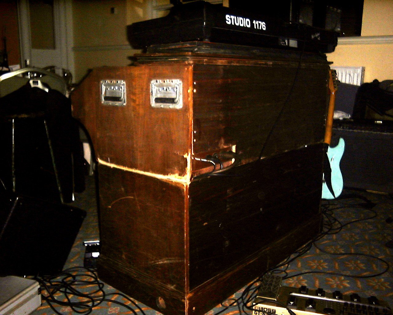
14.1 Teardown & harness labelling
The extraction sequence is designed to maximise access at each stage, document the wiring harness before it is disturbed, and protect sub-assemblies from mechanical damage during extraction. The sequence applies to a standard B-3, C-3, or A-100 console; minor hardware differences (panel-attachment method, harness routing variations across the 1954–1975 production run) may require local adaptation (dairiki.org/HammondWiki, “HammondChops”; organforum.com, general chop community discussion).
The teardown-order flow diagram below maps the extraction sequence, showing dependencies between steps and the point at which the labelling-and-photography gate must be complete before any disconnection proceeds.
14.1.1 Pre-teardown staging
Tools and consumables: DMM with test leads; masking tape, 25 mm (1 in) width; fine-tip permanent marker (black); camera or phone for photographic documentation; pen and notepad; assorted flathead and Phillips screwdrivers; ratchet set with 7 mm, 8 mm, 10 mm, and 12 mm sockets (est. — confirm on the specific unit); socket extension, 150–300 mm (6–12 in); needle-nose pliers; padded work surface (moving blankets or closed-cell foam minimum 50 mm / 2 in thick); plastic zip-lock bags and permanent marker for labelling hardware batches.
Warn: Confirm that the AO-28 B+ rail reads 0 VDC at the B+ bus terminal with the DMM before touching any connector, chassis, or harness lead inside the console. This confirmation must precede every session in the console interior — even if the instrument has been sitting unplugged for a day. A leaky filter capacitor (Vol 08) can retain dangerous charge for an extended period. The check takes thirty seconds; skipping it can be fatal.
- With the console on padded sawhorses or a low rolling cart at approximately 760–910 mm (30–36 in) working height (Vol 06 §“Moving & lifting a console”), confirm the mains cord is unplugged.
- Confirm 0 VDC on the AO-28 B+ rail per Vol 06 §“Capacitor-discharge procedure.” Record the measurement — voltage, time of check — on the notation sheet.
- If the 25-note pedalboard is being retained in the build, remove it from the front of the console now, per Vol 05, and stage it on a separate padded work surface. Label the pedal-contact harness connector before disconnecting it from the console harness.
- Inventory the harness before touching it. Walking the full harness — from the AO-28 chassis to the manual assemblies to the generator connector tray — note every connector group, its approximate location (top rail, console interior left, console interior right, generator top), and the cable colours visible. Sketch a rough map on the notepad.
14.1.2 Photographing and labelling — the critical step
The key-contact harness connecting the manual assemblies to the tonewheel generator tray carries the foldback routing — the wiring that maps 61 keys per manual to 91 tonewheel buses through a shared-bus, overlapping-key-contact matrix (Vol 09 §“The key-contact matrix and foldback”). This routing is encoded entirely in which connector goes to which socket. There is no mechanical keying that prevents a connector from being installed in the wrong socket; no colour-coding that is self-consistent across a twenty-year production run; and no diagram in the publicly available service literature that gives pin-by-pin connector assignments for every production variant.
Warn: Photograph every connector from both sides before disconnecting it. Apply a masking-tape flag to the cable side and a matching flag to the socket side before pulling the connection. Use a consistent labelling code (examples below) and write the code on both sides of every connection. The foldback harness labelling is the most failure-prone step in a chop build: a single transposed connector on the manual-to-generator harness produces incorrect note assignments that can only be corrected by reopening the enclosure and reinspecting the harness. Vol 09 §“The key-contact matrix and foldback” documents the topology and can be used to reconstruct connector assignments if any label is lost — but that reconstruction is a multi-hour task. Labelling is the far cheaper investment.
- Set up photographic documentation. Photograph the full console interior from above (overhead shot showing all harness runs), from each end, and from the AO-28 chassis to its harness connections. Include a scale reference — a ruler or tape measure — in at least one frame per zone. Note the date and console serial number in the file names.
- Label every harness connector group. Working from the top of the console downward, apply a masking-tape flag to each connector and to its mating socket. Suggested naming scheme (adapt to the specific unit):
Table 1 — 6. Label every harness connector group. Working from the top of the console downward, apply a masking-tape flag to each connector and to its mating socket. Suggested naming scheme (adapt to the specific unit)
| Code | Meaning |
|---|---|
AO28-P1 … AO28-P6 | AO-28 preamp harness plug connectors (est. count — varies by year) |
SCN-A / SCN-B | Vibrato scanner connector groups |
EXPR | Expression potentiometer leads |
LST | Leslie run connector / start-run switch leads |
MAN-U-1 … MAN-U-N | Upper manual (Swell) key-contact bus connectors |
MAN-L-1 … MAN-L-N | Lower manual (Great) key-contact bus connectors (dual-manual builds) |
GEN-T1 … GEN-TN | Generator connector tray sockets (the receiving end of the manual harness) |
PWR | Main power conductor to the start/run switch |
- Photograph each labelled connector before disconnecting it — both the cable-side flag and the socket-side flag in the same frame, clearly readable. This two-sided documentation is the recovery path if a label detaches during the build or during transport of the sub-assemblies.
14.1.3 Numbered teardown procedure
-
Remove the music rack by lifting it free of its two support pegs, or by removing the retention screws if it is screwed into position. Bag and label any screws. Set the rack on the padded surface.
-
Remove the AO-28 top access panels — typically 2–4 Phillips or flathead screws per panel (est. — check under the drawbar rail for recessed screws on some production years). Lift each panel clear and set it aside face-up.
-
Remove the drawbar rail hardware. The drawbar rail is typically secured to the manual top rail from below by a series of screws. Locate all retention screws, remove them, and lift the rail clear. The rail carries the expression-pedal bracket on some units — photograph the bracket geometry before removing. Bag all screws by location.
-
Disconnect the expression pedal leads. The expression potentiometer connects to the AO-28 via a two- or three-conductor lead. Label (code
EXPR), photograph, and disconnect. If a compact replacement expression unit will be installed in the new enclosure (common practice in chop builds), the original potentiometer mechanism can be stored as a spare. -
Disconnect and extract the vibrato scanner and run motor. The scanner connects to the line box and to the AO-28 input with two connector groups (est. — confirm on the specific unit). Label each
SCN-A/SCN-B, photograph, and disconnect. Loosen the scanner mounting hardware — typically 2–4 bolts or screws (est.) — and extract the scanner and its run motor as a unit. Do not force or bend the flexible coupling connecting the run-motor shaft to the scanner drum (Vol 10 §“The Vibrato/Chorus Scanner & Run Box”). Lower the assembly onto the padded work surface, motor-end up.
-
Label, photograph, and disconnect the AO-28 harness. With the music rack, access panels, and scanner removed, the AO-28 chassis connections are accessible. Working through each connector group in sequence — key-bus plugs, expression leads (already done), scanner (already done), Leslie/start-run leads — label each
AO28-P1throughAO28-PN, photograph, and disconnect. Note that the AO-28 carries a mix of multi-pin plug connectors and individual push-on (spade) terminals. Apply a masking-tape flag to each spade terminal’s cable lead and to the tab on the chassis it connects to. -
Extract the AO-28 chassis. The chassis is typically secured to the underside of the top rail by 4–6 bolts or screws (est. — confirm on the specific unit). With all harness connections documented and disconnected, support the chassis from below with one hand, remove the retention hardware with the other (or use a helper), and lower the chassis carefully. The AO-28 weighs approximately 15 lb (7 kg) (est., dairiki.org/HammondWiki, “WhatDoesAHammondWeigh”) and carries exposed tube socket pins on its topside. Place it tube-side up on the padded work surface.
- Label and photograph the manual-to-generator harness — both ends. With the AO-28 removed, the key-contact bus harness routing to the generator connector tray at the top of the generator case is now fully accessible. This is the foldback harness (Vol 09) — the most critical label-and-photograph step in the entire teardown. Every connector group must receive a flag on the cable side coded
MAN-U-NorMAN-L-N, and a matching flag on the generator tray socket codedGEN-TN. Photograph each pair in the same frame.
Warn: The manual-to-generator harness determines which of the 91 tonewheel buses each of the 61 key contacts per manual routes to. Reconnecting these connectors in the wrong order will produce incorrect note assignments — potentially every note on the affected manual sounding a tone one or more semitones from its correct pitch. This is not an obvious fault during initial reassembly (the instrument plays; it is simply in the wrong key or partially misassigned) and is extremely difficult to diagnose from outside the enclosure. Photograph both ends of every connector in this group. If a label is lost, use Vol 09 §“The key-contact matrix and foldback” and the Hammond service manual wiring diagram to reconstruct the assignment before reconnecting (dairiki.org/HammondWiki, “Hammond Manual and Tone Generator Wiring Diagram”).
- Extract the upper manual assembly. The upper manual (Swell, 61 keys) is retained to the console frame by a series of screws and brackets at the rear and by the front rail. On B-3/C-3 production units the retention hardware typically includes rear brackets bolted through the console side-cheeks (est. — verify on the specific unit). Remove all retention hardware, then with a helper supporting the assembly from below, slide the manual forward out of the console cavity. The upper manual assembly weighs approximately 48 lb (22 kg) (est., dairiki.org/HammondWiki, “WhatDoesAHammondWeigh”) — a two-person operation. Lower it onto the padded foam work surface, key-top side down, protecting the key surfaces from contact with the worktable.
- Extract the lower manual assembly (dual-manual builds). With the upper manual removed, access to the lower manual (Great, 61 keys) retention hardware is clear. Repeat the same procedure. The lower manual weighs approximately 48 lb (22 kg) (est.). Two-person operation. Place it key-top-down on padded foam.
-
Disconnect the remaining generator harness. With both manuals removed, the generator connector tray at the top of the generator case is fully visible and accessible. Disconnect the remaining labelled connections — start/run motor leads (
PWR), any remaining bus leads — and move the harness clear of the generator case top. -
Extract the tonewheel generator. The generator is typically secured to the console base frame by 4–6 bolts through the generator’s corner mounting feet (est. — confirm on the specific unit). A socket extension of 150–300 mm (6–12 in) is typically required to reach the inner mounting bolts. Two people are required for extraction.
a. Confirm all harness connections to the generator are disconnected and cables are clear of the extraction path. b. Remove all generator mounting bolts. Note the presence and condition of any original rubber isolation washers or grommets at the mounting feet — these are worth retaining if serviceable. c. With one person at each end, lift the generator straight up out of the console cavity. Do not tilt the generator more than approximately 15° from horizontal (see Warn below). d. Lower the generator onto the padded work surface. Maintain approximately horizontal orientation throughout the move. e. Once on the work surface, inspect the oil filler port and cap (Vol 07 §“Oil-filler port and reservoir level”) for any seeping oil or damage incurred during extraction.
Warn: Do not tilt the tonewheel generator more than approximately 15° from horizontal during extraction, handling, or transport. The generator’s oil reservoir feeds the tonewheel bearings by gravity-assisted wicking; when the generator is tilted more than approximately 15° (est., general chop community practice — organforum.com; dairiki.org/HammondWiki), oil migrates from the reservoir toward the tonewheel disc compartment. Oil on the tonewheel disc faces or pickup faces is extremely difficult to remove without complete disassembly of the generator (Vol 07). Move and store the generator level, or tilted only slightly. If a tilting transfer is unavoidable, allow the generator to rest level for at least 30 minutes before powering on, giving oil time to drain back to the reservoir.
- Inventory all extracted sub-assemblies against the Vol 13 Gate 2 checklist. Confirm all connector labels are legible and intact. Photograph the workspace with all sub-assemblies staged on the work surface — this establishes the “before” condition baseline for the Vol 16 build-record entry.
14.2 Designing the portable cabinet
The portable enclosure is a woodworking project governed by two geometric constraints: the extracted sub-assembly dimensions (the manual assemblies set the minimum interior width; the generator bay must fit the generator case with clearance) and the piece-weight targets from Vol 13 §“Weight and piece budget.” All outer dimensions are build-specific and must be derived from the builder’s specific measured sub-assemblies. The dimension ranges below are community-reported typical values (organforum.com; dairiki.org/HammondWiki, “HammondChops”) marked (est.); they are guidance, not a cutting list.
14.2.1 Internal dimension constraints
The enclosure interior must accommodate the specific extracted sub-assemblies with working clearances. Community-reported typical ranges (organforum.com; dairiki.org/HammondWiki) follow — all (est.) and requiring measurement confirmation:
- Manual assembly span (width): the dual-manual assembly including drawbar end brackets measures approximately 54–58 in (1372–1473 mm) end-to-end (est., dairiki.org/HammondWiki; organforum.com, multiple chop build threads). Single-manual: approximately 54–58 in (1372–1473 mm) for the upper manual alone — the manual width does not change between single and dual configuration; the lower manual bay is simply absent. Measure the actual extracted manual assembly end-to-end with all hardware attached before determining the internal width.
- Manual stack height (dual-manual): each 61-key manual assembly is approximately 4.5–6 in (114–152 mm) tall at the key block including the contact bus and wiring below (est. — varies by production year). Allow a minimum of 25 mm (1 in) clearance between the two manuals and between the lower manual bottom and the generator bay ceiling for wiring. Total manual bay internal height: approximately 14–18 in (356–457 mm) (est.).
- Generator case dimensions: the B-3/C-3/A-100 tonewheel generator case measures approximately 17–19 in (432–483 mm) wide, 17–19 in (432–483 mm) deep, and 9–11 in (229–279 mm) tall, excluding the connector tray that adds approximately 2–3 in (51–76 mm) to the top height (est., community measurement — dairiki.org/HammondWiki; organforum.com). Add a minimum of 25 mm (1 in) of air-gap clearance on all faces for wiring, harness runs, and mount hardware.
- AO-28 chassis (if retaining original preamp): the AO-28 measures approximately 18–22 in (457–559 mm) wide, 7–9 in (178–229 mm) deep, and 4–5 in (102–127 mm) tall, plus tube clearance of approximately 3.5 in (89 mm) (est. — measure the specific chassis including tube height). The AO-28 requires ventilation; do not enclose it in a sealed cavity shared with the generator.
- Vibrato scanner and run motor: the scanner assembly spans approximately 10–14 in (254–356 mm) in length (est.); plan a mounting shelf or bracket that does not share a sealed cavity with the generator oil reservoir.
Warn: Do not design the enclosure to the range estimates above without first measuring the specific extracted sub-assemblies. Generator case dimensions, manual-assembly widths with hardware, and AO-28 chassis dimensions all vary across the 1954–1975 production run and across the B-3, C-3, and A-100 families. An enclosure panel cut to a community-range estimate may be undersized for a specific unit’s hardware or oversized at a structural load point. Measure and record all sub-assembly dimensions before writing a cutting list.
14.2.2 Configuration: two-piece vs. one-piece enclosure
Two primary configurations appear in the chop community (organforum.com; dairiki.org/HammondWiki, “HammondChops”):
Two-piece (common in professional and semi-professional builds): The manual assemblies, AO-28 or combo preamp, scanner, drawbar hardware, and controls occupy the main upper enclosure; the tonewheel generator rides in a separate sub-case or generator box. The main enclosure and the generator case travel separately and connect at the venue via a multi-conductor harness (or a connector panel — see Vol 15). Piece weights: main enclosure approximately 120–160 lb (54–73 kg) (est., dual-manual; weight depends heavily on material and preamp choice); generator sub-case approximately 55–75 lb (25–34 kg) (est., including case weight). Each piece is moveable by two people without lifting equipment (organforum.com chop build discussions).
One-piece: Generator bay and manual bay are combined in a single enclosure, with the generator mounted in a sub-bay below the manual section. Reduces piece count at the cost of piece weight — a dual-manual, one-piece enclosure with generator typically weighs approximately 200–250 lb (91–113 kg) (est.), approaching or exceeding the practical two-person carry limit and requiring a dolly or wheels for venue transport. One-piece designs are simpler to wire (shorter harness runs) but harder to stage in a tight venue.
14.2.3 Materials
Baltic birch plywood is the standard enclosure material in the chop community and in road-case construction generally (organforum.com chop build threads; general road-case fabrication practice). Baltic birch is a void-free, multi-ply panel product: at 18 mm (approx 3/4 in) thickness it is a 13-ply construction, and at 12 mm (approx 1/2 in) a 9-ply construction (Woodworkers Source, Baltic Birch reference; Rockler, Baltic Birch Plywood product data). The void-free core makes it structurally predictable at fastener edges, where standard construction plywood often splits or delaminates.
Standard European Baltic birch sheet size: 1525 × 1525 mm (approximately 60 × 60 in) — note this is a 5 × 5 ft sheet, not the North American 4 × 8 ft panel. Plan a cutting layout accordingly.
Table 2 — Materials
| Thickness | Nominal North-American equivalent | Approx. weight per sq ft (est.) | Suggested use in chop enclosure |
|---|---|---|---|
| 12 mm | approx 1/2 in | approx 1.6 lb / 0.73 kg (est.) | Lid, removable back panels, non-load-bearing partitions; use with full-perimeter aluminum-angle framing |
| 15 mm | approx 5/8 in | approx 2.0 lb / 0.91 kg (est.) | General carcass sides on single-manual builds; lighter dual-manual builds with dense corner bracing |
| 18 mm | approx 3/4 in | approx 2.4 lb / 1.09 kg (est.) | Primary structural walls, floor panels, generator bay — the standard choice for load-bearing faces |
Weight per sq ft values above are estimates based on Baltic birch typical density of approximately 680 kg/m³ (42 lb/ft³) (general woodworking reference — Woodworkers Source; Fine Woodworking; est.). Actual values vary by supplier. Weigh a sample panel against a known area before finalising piece-weight budgets.
Aluminum extrusion and angle is used for corner reinforcement and for the generator mounting frame:
- 25 × 25 mm (1 × 1 in) L-angle at 3.2 mm (1/8 in) wall: lightweight corner trim, non-structural edges; attach with countersunk machine screws and threaded inserts in the ply edge.
- 38 × 38 mm (1.5 × 1.5 in) L-angle at 3.2 mm (1/8 in) wall: structural corner bracing on load-bearing corners; also used as the generator mounting ledge (see §“Generator mounting frame”).
- 50 × 6 mm (2 × 1/4 in) flat bar: generator mount cross-members and tie-down brackets.
Road-case hardware — recessed bail handles (rated for the enclosure piece weight; confirm load rating before purchasing), butterfly or slam latches, steel ball-corner protectors, Penn-style caster mounts with 75–100 mm (3–4 in) diameter lockable casters — is appropriate and widely available from flight-case hardware suppliers. Access panels are typically retained by quarter-turn Dzus-type fasteners or recessed butterfly clips for tool-free opening at a venue.
14.2.4 Playing height and stand solution
Standard organ keyboard playing height — the distance from the floor to the top surface of the lower manual keys — is approximately 780–810 mm (30.75–31.9 in) in the original B-3 console leg geometry (est. — organforum.com community discussion; no Hammond factory ergonomic specification has been located in the literature reviewed for this volume). In a chop build, this height is achieved through one of:
- Folding keyboard stand (X-style or Z-style): the lightest and most adjustable approach. The enclosure is placed on the stand and the stand height is adjusted to playing height. Stand load rating must exceed the enclosure piece weight with a safety margin.
- Integral cabinet legs bolted to the enclosure bottom: adds weight but provides a furniture-like appearance and eliminates the stand as a separate piece. Legs must be sized to bear the enclosure load without racking — diagonal bracing or a lower frame rail is advisable.
- Generator-case dolly as sub-frame: in two-piece builds, the generator case rolls on a dolly that also serves as a platform for the main enclosure. The dolly height positions the main enclosure at playing height without a separate stand.
14.3 Building the cabinet
The following procedure describes construction of a two-piece dual-manual enclosure in 18 mm (3/4 in) Baltic birch plywood with aluminum-angle corner reinforcement — the most common approach in the chop community (organforum.com; dairiki.org/HammondWiki). Builders choosing a one-piece enclosure, a single-manual configuration, or an aluminum-frame road case will adapt the sequence accordingly; the underlying joinery and assembly logic remains the same.
Warn: Dry-fit every panel before applying adhesive or driving permanent fasteners. A chop enclosure built around real sub-assembly dimensions has very little tolerance for a mis-cut panel — a panel that is 10 mm (3/8 in) short in width can prevent the manual assembly from fitting or leave the generator inadequately supported. Dry-fit with clamps and check sub-assembly clearances before any glue is mixed.
14.3.1 Tools and consumables
Power tools: circular saw with a quality 60-tooth carbide-tipped blade (or a track saw for clean ply cuts); jigsaw with fine-tooth blade for interior cutouts; router with straight-cutting bit and edge guide for dado joints (optional — butt joints with pocket screws are an acceptable alternative); drill-driver with Phillips and hex bits; countersink bit; orbital sander.
Hand tools: tape measure, combination square, marking gauge, pencil, straightedge, mallet, bar clamps (minimum four at 600 mm / 24 in opening), corner clamps, hammer.
Consumables: carpenter’s PVA glue (yellow woodworking glue); coarse-thread wood screws 35 mm (1-3/8 in) for 18 mm ply; pocket screws 32 mm (1-1/4 in) if using a pocket-hole jig; 40 mm (1-9/16 in) machine screws and threaded inserts for aluminum-angle attachment; waxed paper (caul liner); 120-grit and 220-grit sandpaper; tack cloth; surface treatment (paint, carpet, Tolex — per the builder’s choice); wood glue syringe applicator.
14.3.2 Numbered build procedure
- Finalise the cutting list. From the measured sub-assembly dimensions (§“Internal dimension constraints”) and the configuration decision (§“Configuration: two-piece vs. one-piece”), derive the panel dimensions for: two side panels, top and bottom panels, back panel (access), front panel (with manual openings), any internal partitions (manual-bay floor, generator-bay ceiling), and the generator case panels (if two-piece). Add the wall-thickness allowance (18 mm / 3/4 in per panel where butted) to each dimension. Verify the cutting list fits within the 1525 × 1525 mm (60 × 60 in) Baltic birch sheet size.
- Mark and cut the panels. Using a track saw or a circular saw with a fence guide, cut each panel to dimension. Support the panel fully — Baltic birch at 18 mm (3/4 in) will sag and bind the blade without full support along the cut length. Cut the manual opening(s) in the front panel with a jigsaw: mark the opening from the measured manual-assembly width and height, drill a lead-in hole at each interior corner, and cut with the jigsaw. The opening is the interior dimension of the manual bay — the manual assembly slides into it from the rear.
-
Cut the generator-bay access panel opening in the appropriate face (front of generator bay, rear of main enclosure, or generator sub-case face). The access panel allows removal of the generator for service without dismantling the enclosure. Typical access-panel size: the full generator-face width and height, minus the enclosure-wall framing. Retain the cutout piece — it becomes the access panel itself, rehung on hinges or retained by quarter-turn latches.
-
Sand all panel edges to 120-grit and then 220-grit to remove saw tears and break sharp corners. Wipe with a tack cloth. Do not sand the face veneers of Baltic birch beyond 220-grit at this stage — Baltic birch face veneer is thin, and aggressive sanding burns through to the core.
-
If using dado joints for the interior shelves: rout dadoes across the interior face of the side panels where the manual-bay floor (which also serves as the generator-bay ceiling) will land. A 18 mm (3/4 in) dado, 9 mm (3/8 in) deep, is the standard approach. Dry-fit the shelf into the dado before proceeding. Alternatively, skip the dado and use L-angle cleats or pocket screws for the shelf joint — butt joints are acceptable here.
-
Dry-fit the entire carcass with clamps. With all panels assembled without glue, slide the extracted manual assembly into the manual bay and the generator (or a same-size spacer) into the generator bay. Confirm:
- Manual assembly slides in with 6–12 mm (1/4–1/2 in) clearance per side (est.) — enough for hand clearance but not so much that the assembly shifts during transport.
- Generator clears all walls with the minimum 25 mm (1 in) air gap.
- Access panel opening aligns with the generator face.
- All panels are square (check diagonals — both diagonals of a rectangular box must be equal to within 3 mm (1/8 in)). Resolve any fit issues before proceeding.
- Glue and fasten the main joints. Working one joint at a time, apply a thin, even coat of PVA glue to both mating faces, assemble, and drive 35 mm (1-3/8 in) coarse-thread screws at approximately 150 mm (6 in) centres through the joint. Clamp and allow 60 min minimum dwell under clamp pressure at approximately 20 °C (68 °F) before loading the next panel. Work in a planned sequence: typically bottom + two sides first, then internal shelf, then top.
Warn: Check squareness after every joint — before the glue sets. A racked carcass produces a manual opening that is a parallelogram rather than a rectangle, and the manual assembly will bind on one corner. After driving screws on each joint, measure both diagonals of the assembled box. If the diagonals differ by more than 3 mm (1/8 in), apply racking force (a clamp across the longer diagonal) until they equalise. Hold in position until the glue gels sufficiently to hold squareness without the clamp — typically 15–20 min at 20 °C (68 °F).
-
Install aluminum-angle corner bracing. Drill and countersink the aluminum-angle legs for machine screws at 150 mm (6 in) spacing. Drill pilot holes through the ply panel at matching locations. Drive 40 mm (1-9/16 in) machine screws with threaded inserts installed in the ply edge — do not rely on wood threads alone for the corner-angle attachment, as repeated assembly/disassembly will strip the wood.
-
Hang the access panel. Mount two heavy-duty butt hinges on the access panel and the enclosure face. Use quarter-turn Dzus fasteners or recessed butterfly latches — minimum two per edge of the panel — to retain the panel in the closed position. Confirm the panel swings clear of the generator when opened.
-
Install handles. Recess bail handles are the standard choice for a gigging enclosure. Locate the handles at the balance point of the finished piece — not at the geometric centre, which may not be the weight centre once sub-assemblies are installed. Drill and countersink handle mounting bolts through the full panel thickness. The bail handle mounting hardware must carry the full piece weight; use the manufacturer’s load rating as a lower bound.
-
Install casters. Mount lockable swivel casters rated for at least 1.5 × the expected piece weight at each corner of the bottom panel. Caster mounting hardware: T-nut or threaded insert in the ply bottom, with a backing plate on the interior face if the ply bottom is the sole structural floor.
-
Apply surface treatment. Standard treatments in the chop community (organforum.com): carpet lining (EVA foam-backed road-case carpet, contact-cemented), Tolex vinyl (the traditional Hammond finish match), black ABS laminate, or paint. Carpet provides acoustic damping and impact protection; Tolex provides a more period-correct visual match to the original console finish. See Vol 12 §“Top-coat options” for general finishing parallels; the cabinet-surface treatment on a chop enclosure parallels standard cabinet woodworking finishing practice, with the substitution of contact cement for stapling where carpet is used.
14.4 Manual & generator mounting
With the enclosure shell complete and the sub-assemblies serviced (Vol 13 Gate 4), the manual assemblies and tonewheel generator are installed in the new enclosure. This section documents the mechanical mounting geometry; the harness routing and all electrical connections in the new enclosure are in Vol 15.
14.4.1 Manual assembly mounting
Tools: drill-driver; 3 mm (1/8 in) pilot-bit; countersink; measuring tape; combination square; bar clamps; appropriate screws (32 mm / 1-1/4 in coarse-thread for wood cleats, or M5 machine screws for aluminum cleats).
The manual assemblies mount on cleats — lengths of square-section wood or aluminum angle — fastened to the interior faces of the enclosure side walls. The cleat height positions the manual assembly at the correct playing height and sets the clearance between the two manuals and between the lower manual and the generator bay ceiling. Derive cleat height from the measured sub-assembly stack, not from the community estimates.
- Determine the cleat position for the lower manual. From the generator bay ceiling (the top face of the manual-bay floor panel), measure up by the clearance required below the lower manual (minimum 25 mm / 1 in for harness passage), then place the lower edge of the lower manual mounting cleat at that height. The lower manual assembly rests on this cleat.
- Fasten the lower manual cleats. Drill pilot holes through the enclosure side panel at the cleat position (confirm clearance from the rear wall for the cleat length). Apply a bead of PVA glue to the cleat face, press it to the side panel, and drive 32 mm (1-1/4 in) screws at 100 mm (4 in) centres through the side panel into the cleat. Allow full cure (24 h at 20 °C / 68 °F) before loading.
- Determine the upper manual cleat position. From the top face of the lower manual assembly (as installed), add the inter-manual clearance (est. 6–14 mm / 1/4–9/16 in — enough for the harness to pass between the manuals; measure the specific harness bundle diameter), then add the height of the upper manual assembly. The upper edge of the upper manual assembly must clear the top of the enclosure interior.
- Fasten the upper manual cleats. Repeat step 2 at the upper manual cleat height.
- Slide the lower manual assembly onto its cleats from the front, supporting the assembly weight with a helper. Align the assembly so it is centred in the front opening within 6 mm (1/4 in) per side. Drive one 32 mm (1-1/4 in) screw per side through the cleat into a pre-drilled hole in the manual frame to retain the assembly against forward movement.
- Slide the upper manual assembly onto its cleats. Repeat. Confirm the drawbar hardware, preset keys, and expression bracket clear the enclosure interior on all sides.
Warn: Do not route the manual-to-generator harness or any other wiring in the same channel as the manual assembly without first confirming clearance. The manual assembly slides in from the front for installation and slides out the same way for service. A harness that is run too tightly against the manual assembly will bind the manual on removal, or will be pinched by the manual frame when the assembly is pushed home. Leave a dedicated harness chase of at least 50 mm (2 in) clear diameter between the manual assembly and the nearest harness run (see SVG above).
14.4.2 Generator mounting frame
The tonewheel generator is the heaviest single item in the portable enclosure (approximately 45 lb / 20 kg, est.) and the item most sensitive to mechanical alignment. The generator’s synchronous motor drives 91 tonewheel discs on a common shaft; the tonewheel-to-pickup clearance (Vol 07) depends on the bearing alignment being maintained across the full rotational assembly. A mount that allows the generator to flex, rock, or shift under vibration or transport loading introduces variable tonewheel-to-pickup spacing that produces amplitude modulation (tremolo artifacts) on sustained notes, and in severe cases can cause a tonewheel disc to contact a pickup tab (Vol 07 §“Tonewheel generator — mechanical alignment”).
Warn: The tonewheel generator must be mounted rigidly and squarely in the new enclosure. Rubber isolators are used to decouple generator mechanical vibration (the synchronous-motor hum) from the enclosure panels, reducing transmitted noise; they are not used to allow the generator to move freely. The isolators must be firm enough that the generator does not shift laterally, rock fore-and-aft, or tilt under transport vibration or an accidental impact. Community-reported isolator specification: rubber cylindrical shock mounts rated for approximately 20 lb (9 kg) per mount (est.) with approximately 1/4 in (6.35 mm) centre-bolt hole, capable of resisting lateral displacement from the generator mounting foot without gross deflection — soft Leslie-motor-isolation grommets used as shelf inserts (preventing lateral shift while still providing vertical isolation) are one practical approach (organforum.com chop build discussions; tonewheelgeneral.com, generator mount accessories). If in doubt, use firmer mounts rather than softer: the audible penalty for a slightly over-firm mount is modest mechanical rumble; the audible penalty for a generator that shifts under transport is potential tonewheel contact and possible mechanical damage.
Generator mounting materials: aluminum angle 38 × 38 mm (1.5 × 1.5 in) at 3.2 mm (1/8 in) wall, cut to span the generator bay width; rubber cylindrical shock-mount insulators rated approx 20 lb / 9 kg per mount (4 isolators per generator, one per mounting foot); 1/4 in × 20 tpi (6.35 mm × 1.27 mm/thread) stainless-steel threaded rod or bolts (length to suit the mount stack height); fender washers; nylock nuts; flathead machine screws for the aluminum-angle fastening to the enclosure.
- Fabricate the generator mounting ledge. Cut two lengths of 38 × 38 mm (1.5 × 1.5 in) aluminum angle to span the generator bay interior width. These lengths form the front and rear ledges on which the generator mounting feet rest, via the rubber isolators. Drill clearance holes at 150 mm (6 in) centres for the machine screws that will fasten the ledge to the generator bay floor or side walls, and drill a bolt hole at each generator foot position.
- Measure and mark the generator foot positions. Place the generator (level) in the bay and mark the four mounting-foot locations on the ledge material. Drill 6 mm (1/4 in) clearance holes for the mount bolts at each foot location. Confirm the foot spacing matches the generator’s actual mounting-foot geometry — this is build-specific and must be measured on the specific unit.
- Install the mounting ledge in the generator bay. Fasten the aluminum-angle ledge to the bay floor (or side walls, depending on configuration) with countersunk machine screws and threaded inserts in the plywood. The ledge must be level — check with a spirit level in both axes. Confirm the ledge is fastened firmly: apply hand pressure and confirm no rocking or flex.
- Install the rubber isolators. Place one rubber shock-mount insulator at each generator foot hole on the ledge. If using grommet-style mounts, press the grommet into the ledge hole so it is flush or slightly proud of the ledge top face. Run the mount bolt through the grommet from below.
- Lower the generator onto the mounts. With a helper, lower the generator (level) into the bay until each mounting foot aligns with its isolator and bolt. Install fender washers and nylock nuts on each bolt, and tighten to the isolator manufacturer’s specified torque — if no specification is given, tighten until the rubber is compressed approximately 10–20 % of its free height (est. — general rubber-mount installation practice; do not fully compress the isolator, which would eliminate its isolation function). Confirm the generator is level in both axes with a spirit level on the top face of the generator case.
- Check lateral shift resistance. Apply firm hand pressure to each side of the generator case (front, rear, left, right) and confirm the generator does not shift laterally more than approximately 2 mm (3/32 in) in any direction. If the generator shifts more than this under hand pressure, fit anti-shift tabs — short lengths of aluminum angle or steel bar bolted to the mounting ledge alongside the generator feet, not clamping the feet but preventing lateral travel.
- Verify the generator remains level after loading. With the manual assemblies installed in the enclosure above the generator, re-check the generator level. The weight distribution of the loaded enclosure must not cause the generator to tilt within its mounts.
14.4.3 Manual-to-generator harness routing
Once the manuals and generator are mechanically installed, the harness connectors labelled during teardown (§“Photographing and labelling”) are ready to be routed from the manual assemblies to the generator connector tray. This is the reverse of the teardown disconnect sequence, and the label-and-photograph documentation made during teardown is now the routing map.
Warn: Route the manual-to-generator harness before installing any access panels or closing the enclosure. Route each labelled cable bundle through the dedicated cable chase between the manual bay and the generator bay, confirming that each bundle has at least 25 mm (1 in) of service slack — enough to withdraw the harness clear of the connector tray for future service without disassembling the enclosure. Do not tie-wrap the harness tight against any heat source (the AO-28 chassis, the synchronous motor) — see Vol 15 for the full harness routing and electrical reconnection procedure.
- Route each labelled bundle from the manual assembly through the cable chase to the generator connector tray. Match
MAN-U-Non the cable toGEN-TNon the generator tray socket, confirming the label codes match on both sides before seating the connector. Do not force any connector — if a connector does not seat, confirm the orientation against the teardown photograph before applying additional force. - All other electrical reconnections — AO-28 harness, scanner connections, expression pedal, Leslie switching, and power — are in Vol 15. Do not close the access panels until the Vol 15 electrical work is complete and the instrument has passed the initial power-on check described at the end of Vol 15.
14.5 Weight-reduction choices
Total weight reduction in a chop build is modest — the working sub-assemblies that produce tone (generator, manuals, preamp) represent the majority of the original console mass, and all of them move into the new enclosure (dairiki.org/HammondWiki, “HammondChops” — “not much weight is saved by chopping”). The portability gain is almost entirely from piece-count reduction and piece-weight management rather than from raw mass reduction. Nonetheless, several design choices meaningfully affect enclosure weight, and a few weight-reduction approaches that appear logical are structurally unsafe.
Warn: Do not attempt to reduce weight by lightening the tonewheel generator frame, by using thinner mounting hardware, or by substituting softer isolators to reduce mount mass. The generator frame is a precision casting; any modification to it — drilling additional holes, grinding down structural ribs, removing the cast cover — changes the structural integrity of the assembly and risks misaligning the bearing journals. Generator bearing misalignment causes tonewheel contact, which at 1,200 rpm (at 60 Hz mains) can damage or destroy tonewheel discs, pickup tabs, or both. The generator must be treated as a fixed, unmodifiable assembly. Weight reduction is achieved in the enclosure and accessory choices, not in the sub-assemblies.
14.5.1 Safe weight-reduction approaches
Table 3 — Safe weight-reduction approaches
| Approach | Approx. weight saving (est.) | Trade-off |
|---|---|---|
| 12 mm (1/2 in) ply for lid and back panels vs. 18 mm (3/4 in) throughout | approx 25–35 % panel weight on those panels (est.) | Non-structural panels only; lid and back must still carry access-panel hardware without flexing; add aluminum-angle perimeter framing |
| 15 mm (5/8 in) ply for side walls on a single-manual enclosure | approx 17 % wall-panel weight vs. 18 mm (est.) | Add dense corner bracing; single-manual only — dual-manual enclosure with generator carries too much mass for 15 mm walls without internal reinforcement |
| Aluminum-angle corner bracing replacing solid-wood corner blocks | approx 30–50 % corner-block weight per corner (est.) | Aluminum angle must be correctly torqued to threaded inserts; do not use wood screws alone |
| Omit the original console swell box — replace with compact expression pedal pot | approx 5–8 lb / 2–4 kg (est.) | The swell box is already planned for omission in a chop build; this is the standard approach, not a reduction |
| Single-manual vs. dual-manual | approx 48 lb / 22 kg (est., one manual assembly) | Loss of Swell/Great voicing split — a tonal trade-off, documented in Vol 13 §“Key build decisions” |
| Combo preamp vs. original AO-28 | approx 5–10 lb / 2–5 kg (est., chassis weight difference) | Tonal difference; electronics covered in Vol 15 |
| No tonewheel pedalboard | approx 75 lb / 34 kg (est.) | Loss of authentic tonewheel pedal tone; see Vol 13 §“Decision 5 — Pedals” |
14.5.2 Structural weight reductions to avoid
The following approaches are reported in the general woodworking and road-case community but are not appropriate for a chop enclosure carrying a tonewheel generator:
- Reducing generator bay floor to 12 mm (1/2 in): the generator bay floor carries approximately 45 lb / 20 kg (est.) of generator mass plus the dynamic load of transport vibration. 12 mm (1/2 in) Baltic birch is not adequate as a sole floor panel without a transverse internal frame or a full-perimeter ledge of aluminum angle. Use 18 mm (3/4 in) for the generator bay floor, or 15 mm (5/8 in) with a full-perimeter aluminum-angle ledge system.
- Eliminating access panels to save the panel and hinge hardware weight: access to the generator must be possible without disassembling the enclosure. An enclosure with no access panel commits the builder to removing at least one structural panel to reach the generator for any service, adding hours to every service event.
- Using undersized casters to save weight: caster load rating must exceed 1.5 × the piece weight (est., general road-case practice). Under-rated casters fail under the dynamic load of rolling a loaded enclosure over a door threshold or down a ramp; a caster failure under the full weight of the enclosure drops the generator.
14.6 Reassembly & alignment
With all sub-assemblies mounted, the harness routed, and the Vol 15 electrical connections completed, the final step before first power-on is a mechanical alignment check and a pre-power-on verification pass. This section covers the mechanical alignment checks; Vol 15 covers the electrical verification and initial power-on procedure.
Warn: Do not close the access panels and power on the instrument without first completing the checks in §“Alignment checks” and the Vol 15 pre-power-on verification. An incorrectly mounted generator (off-level or rocking in its isolators) will produce tonewheel-to-pickup contact at speed. A harness connector on the wrong socket will produce wrong notes or no notes — a fault that is electrically harmless but requires reopening the enclosure to resolve. These checks take thirty minutes and avoid hours of fault isolation.
14.6.1 Alignment checks
- Confirm the generator is level in both axes (front-to-back and left-to-right) with a spirit level placed on the top face of the generator case. The generator should read within 2 mm/m (approximately 1/8 in per foot) of level in both axes. If it is off-level, adjust the rubber mount compression (tighten or loosen the mount nuts as needed — see §“Generator mounting frame”, step 5).
- Confirm the generator does not rock under hand pressure. Steady the enclosure and apply firm hand pressure to each generator face. Confirm less than 2 mm (3/32 in) lateral deflection per the §“Generator mounting frame” check. If any deflection exceeds this, add anti-shift tabs before closing.
- Confirm the manual assembly slides smoothly in its mounting cleats. Withdraw each manual assembly by approximately 50 mm (2 in) in the forward direction and confirm it slides without binding. If binding is felt, check for harness pinch points (§“Manual assembly mounting”, step 6) and clear before re-seating.
- Check all harness connector seats. Inspect each labelled connector for full engagement — the connector tab or locking ring must be fully seated. Any connector that is half-engaged will intermittently lose contact under vibration.
- Confirm access panel operation. Open and close the generator access panel. It must swing clear of the generator when fully open and latch securely closed.
- Confirm all handles and casters are secure. Apply the full estimated piece weight equivalent of hand pressure to each handle and confirm no panel flex or pull-through. Roll the enclosure on its casters across the shop floor: confirm the casters roll freely and the locks engage positively.
14.6.2 Initial power-on — forward reference
The initial power-on procedure is in Vol 15. Before proceeding to Vol 15, confirm:
- All harness connectors from teardown are seated per the label codes (
MAN-U-N→GEN-TN, etc.). - All remaining electrical connections (AO-28, scanner, expression, Leslie) have been completed per Vol 15.
- The B+ pre-charge check described in Vol 15 has been passed.
- The generator is confirmed level and the mounts are confirmed non-shifting.
Sources consulted: dairiki.org/HammondWiki — “HammondChops” (definition and overview of chop approaches; note that “not much weight is saved by chopping” and that portability is the goal; two chop methods described — lower-section removal vs. upper/lower separation with tube supports; wire-cut-and-plug approach for harness disconnects; general chop community practice); dairiki.org/HammondWiki — “WhatDoesAHammondWeigh” (generator approx. 45 lb / 20 kg est.; each manual approx. 48 lb / 22 kg est.; AO-28 approx. 15 lb / 7 kg est. — all community weight data flagged (est.) throughout); dairiki.org/HammondWiki — “Hammond Manual and Tone Generator Wiring Diagram” (foldback wiring topology reference; connector mapping recovery path if labels are lost); organforum.com — Hammond chop build discussions including “Plans and Drawings for Hammond Chopped Cabinets” and “B3 Cabinet Woodworking” threads (manual and generator dimension community reports; cabinet materials and construction approaches; rubber-mount approach and Leslie-motor grommet alternative; playing-height target from original leg geometry — all flagged (est.) as community data); organforum.com — “Northern Hammond CV frankenorgan update” and related threads (generator isolation details; rubber mount approach; shock-mount load rating approximately 20 lb per mount est.); tonewheelgeneral.com (generator mount accessories; shock-mount kit reference); bossorgan.com (combo preamp as AO-28 substitute in chop builds — referenced in Vol 13 and forward-referenced here for the Vol 15 electronics); bborgan.com — Northern Chop product page (professional chop builds; no technical dimensions published — confirms that chop enclosure geometry is fully build-specific); Woodworkers Source — Baltic Birch Plywood reference (void-free construction; ply count at each thickness; European 5 × 5 ft sheet size); Rockler — Baltic Birch Plywood product data (thickness options: 9-ply at 1/2 in / 12 mm; 13-ply at 3/4 in / 18 mm); general woodworking practice — PVA glue cure times, dado joints, pocket screws, grain-sanding direction, grain filling, topcoat options (paralleled with Vol 12 §“Stripping, staining and top-coat” for the finishing cross-reference); general road-case construction practice — aluminum-angle corner bracing, butterfly latches, Dzus fasteners, Penn casters, handle load rating (est. 1.5 × piece weight); general rubber-mount installation practice — isolator compression target approx 10–20 % of free height (est.); groupdiy.com — “Hammond B3 Chop” thread (scanner and line box as commonly missing sub-assemblies; general chop assembly experience; referenced in Vol 13 for those details; teardown principles apply here). Cross-references: Vol 06 §“Moving and lifting a console” (console weight approx 310 lb / 141 kg est.; lifting procedure; B+ discharge procedure before any internal work); Vol 07 §“Tonewheel generator — mechanical alignment” and §“Oil-filler port and reservoir level” (generator oil migration on tilt; tonewheel-to-pickup clearance; service before installation); Vol 08 §“Power supply and safe discharge” (B+ rail approximately +200 VDC; discharge procedure; filter capacitor hazard); Vol 09 §“The key-contact matrix and foldback” (foldback topology; manual harness connector mapping; recovery procedure if labels are lost); Vol 10 §“The Vibrato/Chorus Scanner and Run Box” (scanner extraction; flexible coupling; run motor); Vol 12 §“Top-coat options” and §“Stripping, staining and top-coat” (finishing cross-reference for the enclosure surface treatment); Vol 13 §“Weight and piece budget”, §“Key build decisions”, §“A chop project checklist” (all planning decisions that gate this volume; piece-weight targets; Gate 2 inventory; Gate 4 service triage); Vol 15 (preamp wiring, power supply, scanner re-connection, Leslie switching, and initial power-on in the portable enclosure — not covered here); Vol 16 (build-record gallery — teardown photos, build sequence photos, and first-play record for this chop); Vol 18 (reference cheatsheet and bibliography). All generator and manual sub-assembly weight figures are (est.) from community sources (dairiki.org/HammondWiki); no factory-specification breakdown of Hammond B-3 console sub-assembly weights by component has been located in the service literature reviewed for this volume. All cabinet dimensions are (est.) community ranges and carry [YOUR BUILD] annotations throughout — no canonical chop enclosure specification exists and every build must be designed to fit the specific extracted sub-assemblies.
Comments (0)