Hammond B-3 · Volume 11
Hammond B-3 — Vol 11: Leslie 122 Service
This volume is the bench refurbishment manual for the Leslie 122 cabinet — the service complement to Vol 04, which established the rotary acoustic theory, 6-pin balanced interface, speed-switching circuit, tube complement, supply rails, crossover physics, and rotor anatomy. None of that theory is re-derived here; cross-references point back to Vol 04 wherever the background is needed. What Vol 04 explicitly deferred to “Vol 11 §11.x” is documented here: recapping and verifying the bias of the 40 W tube amplifier, cleaning and testing the speed relay and 6-pin connector, replacing drive belts, oiling the rotor motors, and servicing the rotor bearings. Safety prerequisites — mains hazards, the AC death-cap removal, the B+ capacitor-discharge procedure, and the variac ramp — are in Vol 06. The analogous cotton-wick oiling system in the Hammond console generator is covered in Vol 07 and provides useful contrast to the Leslie’s felt-pad motor bearings. Mic’ing the rotating field is Vol 17; the reference tube and specification tables are Vol 18.
Warn: The Leslie 122 amplifier develops B+ rails of approximately +415 VDC to +430 VDC (bentonelectronics.com; Vol 04 §“The 40 W amplifier”). These rails are stored on the four-section filter capacitor and persist after power-off and after the 6-pin cable is disconnected. A charge at these potentials is lethal. Before any internal work on the amp chassis, the supply must be discharged and confirmed at 0 VDC at every section per the procedure in Vol 06 §“Capacitor-discharge procedure.” The 6-pin cable carries AC mains on pins 3 and 4 and approximately +300 VDC on pin 5 (Vol 04 §“The 6-pin balanced interface”); disconnect it only with the complete system fully powered down. The output tubes run physically hot; allow a minimum of 15 minutes of cool-down before handling the 6550A pair.
11.1 Amp recap & bias
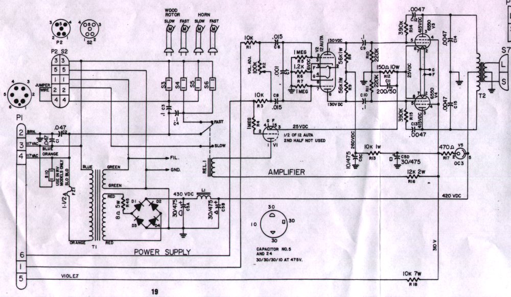
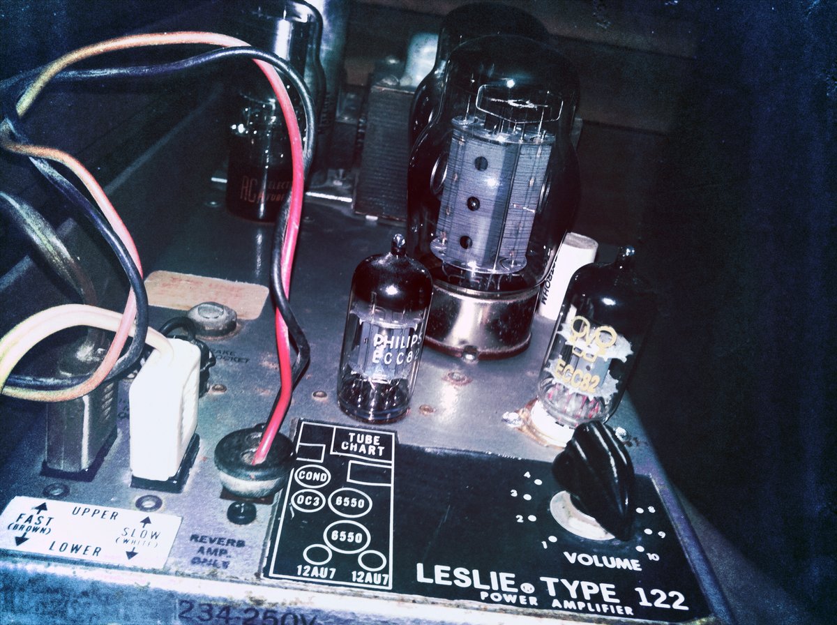
The 122 tube amplifier is a ~40 W push-pull single-channel design (bentonelectronics.com, “Servicing the Leslie 122 Amplifier”; en.wikipedia.org, “Leslie speaker”). Its tube complement — one 12AU7A (dual-triode driver, phase-splitter, and speed-switching detector), a matched pair of 6550A pentodes (output stage), and one OC3 gas-discharge voltage regulator — is confirmed against the 122/142 amplifier service literature and is consistent with Vol 04 §“The 40 W amplifier.” Rectification is provided by a solid-state silicon diode bridge on the great majority of production units; a rectifier tube is found only on the earliest examples (bentonelectronics.com). Supply rails and tube operating points are tabulated in Vol 04 §“The 40 W amplifier”; the essential service values are collected in the inventory table below.
Warn: The B+ reservoir section of the filter can measures approximately +430 VDC at normal operation (bentonelectronics.com). This charge persists on the capacitor after power-off and after the 6-pin cable is disconnected. Discharge and verify 0 VDC at every section of the four-section filter can per Vol 06 §“Capacitor-discharge procedure” before unsoldering any component, probing any node below the rectifier output, or removing any tube. Use a discharge-resistor tool (10 kΩ to 25 kΩ wirewound, ≥ 25 W — at +430 V across 10 kΩ the dissipation is +430² / 10 000 ≈ 18.5 W; a 25 W unit is the minimum safe rating for this rail) and a DMM on the 1 000 VDC range. Re-measure every section after any work pause — dielectric soak can recover a partial charge. Never discharge with a bare conductor or screwdriver.
11.1.1 Tube & capacitor inventory
Table 1 — Tube & capacitor inventory
| Component | Type / value | Voltage rating | Notes |
|---|---|---|---|
| V1 | 12AU7A dual triode | Plates ~+130 VDC | First triode: balanced input amplifier and phase-splitter (drives 6550A grids). Second triode: speed-switching detector — grid coupled via 1 MΩ to audio pair; cathode biased at ~+25 VDC (Vol 04 §“The 40 W amplifier”; bentonelectronics.com) |
| V2, V3 | 6550A matched pair | Plates ~+415 VDC | Push-pull Class AB output; always replace as a matched pair from a reputable supplier (bentonelectronics.com) |
| V4 | OC3 gas-discharge regulator | Drops ~105 VDC → output ~+310 VDC | Pin 2 current-limiter: 470 Ω, 0.5 W resistor (bentonelectronics.com). Glows orange-red in operation — normal |
| Rectifier | Silicon diode bridge | Input from mains transformer secondary | Solid-state on the great majority of production units (bentonelectronics.com; Vol 04) |
| Main filter cap | 4-section can: 30/30/30/10 µF @ 475 WVDC | 475 VDC max per section | Original Mallory FP can type. Replacement: CE Mfg C-EC30-30-30-10 or equivalent (amplifiedparts.com; opentip.com). Second section operates at ~+420 VDC — highest-stress section |
| Feedback / coupling cap | 0.0047 µF / 1 600 VDC film | 1 600 VDC | Between 12AU7A pin 3 and pin 5 via 390 kΩ resistor. Known leaker in the CDE “green” moulded family; a leaking cap shifts grid bias and causes distortion (bentonelectronics.com) |
| Driver-to-grid coupling caps | CDE “green” moulded film caps | Per unit schematic | Between 12AU7A driver output and each 6550A control grid. Widely reported failure population; check for DC leakage in-circuit before assuming the tubes are bad (bentonelectronics.com; organforum.com) |
| Cathode bypass cap | Per unit schematic (read from chassis) | Rated for cathode service | Across the shared 150 Ω cathode resistor. A failed open bypass cap raises AC in the cathode circuit and increases distortion |
| Shared cathode resistor | 150 Ω wirewound | — | Carries combined cathode current of both 6550A tubes. Wrong value (e.g. 125 Ω) overdrives the tubes (organforum.com); confirm in-circuit with B+ at 0 VDC |
Sources: bentonelectronics.com (“Servicing the Leslie 122 Amplifier”); Vol 04 §“The 40 W amplifier”; amplifiedparts.com and opentip.com (CE Mfg 30/30/30/10 µF @ 475 V part data); organforum.com (“6550 Bias Measurement”).
11.1.2 Amp service block — tube layout & measurement points
11.1.3 Recap procedure
Tools required: temperature-controlled soldering iron (25 W to 60 W, chisel tip); desoldering braid and vacuum solder sucker; DMM (1 000 VDC range); discharge-resistor tool (25 W minimum, 10 kΩ to 25 kΩ wirewound); ESR meter (PEAK ESR70 or equivalent); long-nose pliers; diagonal cutters (flush-cut); inspection mirror and magnifier; isopropyl alcohol (≥ 90 %); lint-free cotton cloths; replacement 4-section filter can (30/30/30/10 µF @ 475 WVDC or higher); replacement coupling / feedback caps (≥ original capacitance value, ≥ original WVDC rating); heat-shrink tubing (3.2 mm / ⅛ in and 6.4 mm / ¼ in); anti-static wrist strap.
Prerequisites: mains off and mains cord unplugged; 6-pin cable disconnected from cabinet; amp chassis removed from cabinet and on an insulated work surface; B+ rail discharged and confirmed at 0 VDC at every section of the filter can per Vol 06 §“Capacitor-discharge procedure.”
- Discharge and verify the filter can. Set DMM to 1 000 VDC. Measure from the highest-voltage section terminal (reservoir, ~+430 VDC when charged) to chassis ground. Apply the discharge- resistor tool across the cap section; observe the voltage fall on the DMM. Move through all four sections individually. Confirm each reads 0 VDC; wait 60 s and re-measure to detect dielectric-soak recovery. Do not proceed until every section is confirmed at 0 VDC.
- Photograph all wiring before unsoldering. Record orientation, lead routing, and which terminal each cap lead connects to. A polarity reversal on an HV electrolytic causes immediate failure on power-up.
- ESR-test each section of the filter can in circuit (at 0 VDC). Bridge the section’s negative terminal to chassis with a clip lead to stabilise the measurement. A healthy section reads below approximately 5 Ω ESR; readings above 15 Ω indicate a failing section. A section reading correct ESR but below 70 % of its nominal µF value has compromised dielectric and should be replaced. Replace the entire can if any section fails — partial-section failure is a predictor of imminent failure in adjacent sections.
- Check DC leakage across each coupling cap. With B+ at 0 VDC, temporarily re-apply a controlled low voltage across the coupling cap under test (using a bench supply set to 12 VDC) and measure the leakage current — or, after verifying safe operating conditions, measure DC voltage across each cap at normal operating voltages (live work; see WARN below). Any DC reading above approximately 0.2 VDC across a capacitor intended to block DC indicates leakage. Prioritise the 0.0047 µF / 1 600 VDC feedback cap (between 12AU7A pins 3 and 5 via 390 kΩ) and all CDE “green” moulded coupling caps between the driver and 6550A grids (bentonelectronics.com).
- Remove the filter can. Unsolder all four section leads; note the mounting bracket arrangement and retain the original bracket if the replacement is the same form factor. Extract the can without levering against adjacent wiring.
- ESR-test and inspect the cathode bypass cap (across the shared 150 Ω cathode resistor). Remove one lead; measure ESR and capacitance against the schematic value. Replace if ESR is elevated or capacitance is below 70 % of nominal.
- Install all replacement caps. Observe polarity throughout. Solder each lead with fresh 63/37 or 60/40 Sn/Pb rosin-core solder; a correct joint is smooth and bright. Trim leads flush. Wipe flux residue with isopropyl alcohol; allow to dry.
- Verify all polarity markings on all replaced caps — a final check before power-up.
- Ramp via variac (Vol 06 §“Powering up a long-stored instrument”) at approximately 10 V AC per minute from 0 V to 120 V AC. Watch for any pop, hiss, burning odour, or current surge. If the filter can vents, set the variac to 0 V immediately and diagnose.
- Verify supply rails at full mains (120 V AC / 60 Hz). Expected readings (bentonelectronics.com; Vol 04 §“The 40 W amplifier”):
Table 2 — (bentonelectronics.com; Vol 04 §"The 40 W amplifier")
| Supply node | Nominal |
|-------------|---------|
| Rectifier output (reservoir section) | ~+430 VDC |
| After filter choke | ~+420 VDC |
| 6550A plates | ~+415 VDC |
| OC3-regulated screen / driver rail | ~+310 VDC |
| Preamp section (after 10 kΩ dropping resistor) | ~+260 VDC |
| 12AU7A plates (both triode sections) | ~+130 VDC (est.) |
Warn: Verifying supply rails (step 10) is live work at B+ potentials up to +430 VDC. Use 1 000 V-rated test leads; keep one hand clear and free; stand on an insulated mat; remove all jewellery from the working hand. Avoid any body contact with the chassis frame — if the amp is removed from the cabinet and sitting on a bench, clip a safety ground strap from the chassis frame to the bench ground rail before applying mains. Do not contact two nodes simultaneously with bare probe tips.
11.1.4 Retube procedure
Prerequisites: recap complete; chassis cooled (at least 15 minutes after any prior power-on); B+ confirmed at 0 VDC.
- Allow a minimum of 15 minutes after any power-down before handling the 6550A pair — tube glass is hot enough to cause burns.
- Remove the 6550A pair. Grip each tube at the base (not the glass). Pull straight up without rocking; rocking can damage socket pins.
- Remove the 12AU7A and OC3 by the same method.
- Inspect tube sockets. Bent or oxidised socket contacts cause intermittent operation and bias error. Straighten bent contacts gently with a small flat-blade screwdriver; clean oxidised contacts with residue-free contact cleaner (DeoxIT D5 or equivalent); allow to dry fully.
- Install the new matched 6550A pair. Press each tube firmly and evenly into its socket without rocking. A misaligned pin can bend a socket contact permanently.
- Install the 12AU7A and OC3 by the same method.
- Perform bias verification (next section) before extended operation.
Warn: The 6550A output tubes each dissipate approximately 32 W at the design bias point (calculated: Vak ≈ 390 V × Ia ≈ 83 mA ≈ 32.4 W; consistent with bentonelectronics.com cathode voltage target and organforum.com bias-current data). The 6550A is rated for approximately 35 W plate dissipation. Operating with the wrong cathode resistor value — for example, 125 Ω rather than the correct 150 Ω — increases idle current and pushes the tubes beyond their safe dissipation limit (organforum.com, “6550 Bias Measurement”). Confirm the cathode resistor reads 150 Ω ± 5 % in-circuit at 0 VDC before powering up with a new tube pair. Do not substitute EL34, KT88, or 6L6GC without verifying compatibility with the cathode-resistor value, socket pinout, and output-transformer primary impedance — the 122 amp is designed around the 6550A specifically.
11.1.5 Bias verification
The Leslie 122 uses cathode bias (self-bias): the operating point is set by the shared 150 Ω cathode resistor and the tubes’ own characteristics, not by an adjustable trimmer pot. There is no bias potentiometer in the 122 amplifier. A closely matched 6550A pair will self-bias to near the design point automatically — this makes the circuit “plug-and-play” for tube replacement, provided the tubes are well-matched and the cathode resistor is the correct value (organforum.com; bentonelectronics.com). Bias verification confirms the tubes are operating in the correct range after a retube.
Tools: DMM (DC volts, 200 VDC range); 1 000 V-rated test leads.
Prerequisites: recap complete; correct 150 Ω cathode resistor confirmed; chassis powered and at operating temperature (allow 5 minutes of idle warm-up after power-on).
- Locate the shared 150 Ω cathode resistor between the common-cathode junction of the 6550A pair and chassis ground (consult the unit’s own schematic — it is visible in the leslie_122_amp_schematic.jpg figure above).
- Set DMM to DC volts (200 VDC range). With the chassis powered (all safety precautions active per WARN below), measure DC voltage from the top terminal of the 150 Ω resistor to chassis ground.
- Expected reading: approximately 25 VDC (bentonelectronics.com). This corresponds to:
- Total cathode current: 25 V ÷ 150 Ω = 167 mA (both tubes combined)
- Per-tube idle current: ~83 mA at the design point (bentonelectronics.com; organforum.com)
- In practice, the higher plate voltages of production units often yield approximately ~93 mA per tube (est.; organforum.com), giving a cathode voltage of approximately 27–28 VDC — still within the acceptable range.
- A reading between 22 VDC and 30 VDC is generally acceptable with a new matched pair.
- A reading below 18 VDC (tubes running cold) or above 35 VDC (tubes running hot) warrants investigation.
- If the cathode voltage is out of range:
- Confirm the 150 Ω cathode resistor value in-circuit at 0 VDC — a drifted or wrong-value resistor is the most common cause; replace if measured value deviates more than ±10 %.
- Confirm the cathode bypass cap is not open (an open bypass cap does not affect the DC cathode voltage but does increase AC in the cathode circuit; measure ESR in-circuit).
- If the resistor and bypass cap are correct but the cathode voltage is persistently out of range, source a better-matched 6550A pair from a different supplier lot.
- Verify 12AU7A plate voltages. Measure from pins 1 and 6 (12AU7A) to chassis ground; expect approximately +130 VDC each (est.; bentonelectronics.com). A 5–10 VDC difference between the two triode sections is acceptable (bentonelectronics.com).
- Verify 6550A grid bias. Measure at pin 5 of each 6550A (control grid) to chassis ground; with a healthy bias condition this reads below 1 VDC (bentonelectronics.com). A reading well above 1 VDC indicates a leaking coupling cap applying DC to the grid — find and replace the leaking cap.
Warn: Bias verification is live work at B+ potentials of +415 VDC to +430 VDC. Follow all live-chassis safety precautions from Vol 06: one hand behind the back or in a pocket, standing on an insulated mat, no jewellery, 1 000 V-rated test leads with insulated probe tips. Use only single-point probe contact — touching two nodes simultaneously with bare probes can result in a short-circuit fault through the body. Keep the discharge-resistor tool immediately to hand.
11.2 The speed relay & 6-pin signalling
The speed-switching circuit — common-mode DC on the balanced audio pair, detected by the 12AU7A switching triode (V1b), energising the chorale motor relay — is fully derived in Vol 04 §“The 6-pin balanced interface & speed signalling” and §“Speed-switching circuit.” The 6-pin pinout (captain-foldback.com) and the signal-flow block diagram are in Vol 04 and are not repeated here. This section covers the service work only: cleaning the 6-pin connector, cleaning and testing the relay contacts and coil, and verifying the switching voltages.
Warn: The 6-pin Leslie cable carries AC mains on pins 3 and 4 and approximately +300 VDC on pin 5 alongside the audio and speed-control signals (Vol 04 §“The 6-pin balanced interface”; captain-foldback.com, “Uncle Harvey’s guide to Leslie pin-outs”). This cable is not a low-voltage signal lead. Mate and de-mate it only with the complete system fully powered down, the mains cord unplugged, and B+ at 0 VDC. Never probe the open connector face with a bare meter probe — a mis-contact on the live connector places a probe in contact with AC mains or +300 VDC.
11.2.1 Speed relay & 6-pin signalling — service diagram
11.2.2 6-pin connector cleaning
Dirty contacts on the 6-pin Amphenol cause intermittent audio, loss of one leg of the balanced pair, failed speed changes, or — if the mains pin contacts have eroded — arcing on power-up (bentonelectronics.com; Vol 06 §“Common Leslie faults”).
Tools: residue-free contact cleaner (DeoxIT D5 or equivalent); fine cotton swabs; bright work light; 10× magnifier; DMM (resistance, 200 Ω range).
Prerequisites: system fully powered down, mains cord unplugged, B+ at 0 VDC.
- Inspect the connector face for bent, corroded, or missing pin contacts; cracked housing; evidence of arc pitting. Any physical damage warrants full connector replacement.
- Clean the plug contacts. Apply contact cleaner to a fine cotton swab; wipe each pin contact firmly several times. Allow to dry completely before re-mating.
- Clean the socket contacts in the same manner; rotate the swab to reach the socket walls.
- Measure contact resistance. With a DMM on the 200 Ω range, measure from the plug pin tip to the corresponding wire at the far end of the cable for each of the six pins. Any pin showing resistance above 1 Ω indicates a contact that cleaning alone may not resolve; consider re-pinning or replacing the connector.
- Inspect the cable jacket along its full length, particularly at the cabinet strain relief and at the Amphenol backshell. Cracking or abraded insulation near the AC mains conductors (pins 3 and 4) is a shock hazard and requires the entire cable to be replaced.
11.2.3 Relay cleaning & testing
The speed-changeover relay selects the slow (chorale) motor pair when energised and falls back to the fast (tremolo) pair by default (de-energised). Dirty or oxidised contacts are the primary cause of “Leslie stuck on one speed” faults (bentonelectronics.com).
Tools: residue-free contact cleaner; thin non-abrasive contact card or lens-cleaning paper; DMM (resistance, 20 kΩ range; DC volts, 200 V range).
Prerequisites: B+ at 0 VDC (confirmed at filter can); chassis on the bench.
- Locate the relay on the amp chassis (visible in the leslie_122_amp_chassis.jpg figure).
- Inspect contacts under magnification. Dull or blackened contact faces indicate oxidation; bright surfaces indicate clean contacts.
- Clean contacts. Pass a strip of non-abrasive contact card lightly moistened with contact cleaner between the contact faces; draw through several times. Do not abrade the contact surface — abrasion removes the precious-metal contact plating.
- Test coil resistance. Measure across the relay coil terminals with DMM on resistance range. Expected range for this class of relay is approximately 500 Ω to 3 kΩ (est.) — the exact value is in the unit’s own service data. An open circuit (OL) means the coil is broken and the relay cannot energise; replace the relay.
- Verify speed switching at operating point. With the cabinet connected to a powered console via the 6-pin cable: in chorale mode, a switching voltage of approximately +35 to +60 VDC (est.; bentonelectronics.com; lambertsmusicsolutions.com) should be detectable at the 12AU7A V1b switching-triode grid (via the 1 MΩ coupling resistor) — the relay should energise and the slow motors should run. Switching to tremolo mode should drop this voltage to approximately 0 VDC, allowing the relay to drop out and the fast motors to run.
- Confirm both speeds acoustically. Treble horn reaches full tremolo speed (~400 rpm, ≈ 6.7 Hz audible modulation) and full chorale speed (~40–50 rpm, ≈ 0.7–0.8 Hz) (Vol 04 §“Chorale vs tremolo”). Speed transition takes approximately 5–8 seconds as the rotor inertia ramps (bentonelectronics.com; see §“Motors, belts & oiling”). A noticeably faster transition (1–3 s) suggests a slipping or contaminated belt rather than normal operation.
11.3 Motors, belts & oiling
Each of the two rotors — the treble horn assembly and the bass drum baffle — is driven by a two-speed motor stack: a fast (tremolo) motor and a slow (chorale) motor, each connected to the rotor shaft through a rubber or polyurethane drive belt. The motor relay (§“The speed relay & 6-pin signalling” above) energises one motor pair or the other; the rotor’s rotational inertia then ramps it to the new speed over approximately 5–8 seconds (bentonelectronics.com) (Vol 04 §“Chorale vs tremolo”). For service reference, the rotor speed table from Vol 04 is reproduced here:
Table 3 — reproduced here
| Rotor | Chorale (slow) | → Hz | Tremolo (fast) | → Hz |
|---|---|---|---|---|
| Treble horn | ~40–50 rpm (est.) | ~0.7–0.8 Hz | ~400 rpm | ~6.7 Hz |
| Bass drum | ~40 rpm (est.) | ~0.67 Hz | ~340 rpm | ~5.7 Hz |
Sources: en.wikipedia.org (Leslie speaker); organforum.com; hammondorganco.com owner’s manuals. Chorale figures marked (est.) — consistent with Vol 04 §“Chorale vs tremolo.”
Warn: Open the Leslie cabinet only with the system fully powered down and the 6-pin cable disconnected (pins 3 and 4 carry AC mains). Before accessing any compartment that borders the amp chassis, confirm B+ at 0 VDC (Vol 06). Rotor assemblies have substantial rotational inertia and can continue spinning for up to 30 seconds after power-down — never reach into a compartment with a rotor that may still be rotating. Wait for full stop before opening either compartment.
11.3.1 Motor/belt/rotor drive layout
11.3.2 Drive belts
The rubber and polyurethane drive belts perish, glaze, stretch, and crack with age. A perished or glazed belt is the most common cause of a rotor that cannot reach full tremolo speed, a rotor that spins slowly or erratically, or a rotor that will not start at all. Belt replacement is the first service step on any unserviced Leslie 122.
Table 4 — Drive belts
| Belt | Rotor driven | Length | Material | Replacement source |
|---|---|---|---|---|
| Upper drive | Treble horn | 25.5 in (648 mm) | Rubber, no seam | amplifiedparts.com; tonewheelgeneral.com |
| Lower drive | Bass drum | 31 in (787 mm) | Polyurethane, sanded seam | amplifiedparts.com; tonewheelgeneral.com |
Sources: amplifiedparts.com product listings “Belt - Leslie, Upper Drive, 25.5 in, for 122/147, Rubber” and “Belt - Leslie, 31 in, Lower Drive, for 122/147, Polyurethane” — VERIFIED.
Tools: snap-ring pliers (if fitted on rotor shaft collar); long-nose pliers; clean cotton rags; isopropyl alcohol (≥ 90 %).
Prerequisites: system fully powered down, 6-pin cable disconnected, rotors fully stopped.
- Access the horn compartment. Remove the top panel of the upper compartment (typically four screws on the cabinet top). Ensure the horn has fully stopped before reaching in.
- Lift the old upper belt off the motor pulley and rotor spindle groove. Inspect the pulley groove for glazing or contamination; wipe both the motor pulley and the rotor spindle drive surface with isopropyl alcohol on a cotton rag. Allow to dry completely before fitting the replacement.
- Fit the new 25.5 in (648 mm) rubber upper belt. Route over the motor pulley first, then stretch carefully over the rotor spindle. Do not use sharp tools to lever the belt on — a nick creates a stress riser that causes early failure.
- Access the drum compartment through the lower panel or side access (cabinet-revision dependent).
- Remove the old lower belt from the drum motor pulley and drum rotor drive ring. Clean the pulley and drive ring as above.
- Fit the new 31 in (787 mm) polyurethane lower belt. Route carefully into the drive-ring groove; the longer, more flexible belt has more slack — confirm it is fully seated in its groove before reassembling.
- Verify belt tension at power-up. After reassembling and confirming the amp section is safe, power the cabinet and observe the speed transition time between tremolo and chorale. A correctly tensioned belt produces a transition time of approximately 5–8 seconds (bentonelectronics.com, “Servicing the Leslie Motors”). A slipping belt gives erratic run-up or failure to reach full speed. An over-tight belt strains the motor bearings. Belt position on the pulley can be adjusted to achieve the correct tension — three belt-height positions are typically available (hammondorganco.com, 122A/122XB/147A owners manual).
11.3.3 Motor oiling
Each of the four AC induction motors (two per rotor: fast and slow) uses sleeve (Oilite) bearings fed from a felt-pad oil reservoir inside the motor end covers (bentonelectronics.com, “Servicing the Leslie Motors”). The felt pads wick oil to the bearing surface; they need moistening — not flooding — at approximately yearly intervals under normal use. This is the felt-pad system; it is fundamentally different from the Hammond console generator’s cotton-wicking system (Vol 07), which uses capillary threads that travel through the instrument and which requires only Hammond tonewheel oil. The Leslie motor felt pads tolerate a wider choice of oil.
Oil type: Leslie oil (sold by Hammond distributors and the restoration trade) or, where Leslie oil is unavailable, light non-detergent machine oil such as sewing-machine oil (bentonelectronics.com, “Servicing the Leslie Motors”). Do not use 3-in-1 household oil, detergent motor oil, or multigrade automotive oil — these gum the felt pad and promote contamination.
Warn: Over-oiling is the most common and most damaging motor-service error. Each felt pad absorbs only a limited quantity; any excess that the pad cannot hold is flung outward by centrifugal force onto the drive belts and rotor surfaces, glazing the belt surface (causing slip), contaminating the rotor drive ring, and potentially reaching the rotor bearings. Oil sparingly — the target is a moistened pad, not a saturated one. Apply 2 to 4 drops only; wait 30 seconds for absorption before reassembling (bentonelectronics.com, “Servicing the Leslie Motors”).
Tools: Leslie oil or light non-detergent sewing-machine oil; precision oil applicator or fine-tip eyedropper; cotton rags; small flat-blade screwdriver (for motor end-cover screws); small snap-ring pliers (for motor shaft C-clamp if fitted).
Prerequisites: system fully powered down, 6-pin cable disconnected, B+ at 0 VDC, rotors at full stop, motor electrical leads labelled and disconnected.
- Remove the motor from its mounting bracket. On the fast motor, remove the “C” clamp on the motor shaft and lift the motor free; retain the drive pulley and any shims in their original positions. Label each motor lead before disconnecting.
- Remove both end covers (typically two screws per cover). Inside each end cover is a felt pad surrounding the shaft opening.
- Inspect each felt pad. A clean, moist-looking pad is correctly maintained. A dry or crystallised pad (gummy, discoloured) should be cleaned with a small amount of isopropyl alcohol, dried completely, then re-oiled. A heavily degraded pad may need replacement — source replacement felt from the restoration trade (tonewheelgeneral.com; goffprof.com).
- Apply oil. Add 2 to 4 drops of Leslie oil (or sewing-machine oil) to each felt pad; allow 30 seconds for absorption. Do not pour freely — a saturated pad will eject excess.
- Check the slow-motor armature spring. The slow motor has a spring on the armature that centres the armature at rest. This spring “will lose some of its strength over time,” causing the armature to bottom out when switching speeds and producing a clunking sound (bentonelectronics.com, “Servicing the Leslie Motors”). Inspect the spring for set (permanent compression) or breakage; replace if weak or absent.
- Reassemble end covers and reinstall the motor on its bracket. Re-attach electrical leads and the shaft C-clamp.
- Re-fit the drive belt (§“Drive belts”) and verify the 5–8 second transition time after power-up.
11.4 Crossover & drivers
The 800 Hz passive LC crossover splits the amplifier output: above 800 Hz to the Jensen compression horn driver, below 800 Hz to the 15-inch (381 mm) woofer. Acoustic rationale and theory are in Vol 04 §“Crossover & drivers.” The crossover is wired for the cabinet’s specific driver impedances — the 15-inch woofer at 16 Ω nominal (bentonelectronics.com; Vol 04) and the Jensen driver — and the exact inductor and capacitor values are in the unit’s own service schematic; they are not restated as bare numbers here.
Warn: The crossover network is wired directly to the amplifier output transformer. The amplifier B+ must be at 0 VDC and the chassis must be fully powered down and cooled before probing or unsoldering any crossover component. An unsoldered output transformer winding retains an inductive kick potential until it is confirmed open-circuit. Do not probe the output transformer secondary or the crossover with the amp live unless using a properly isolated audio probe with an in-series capacitor rated above the maximum voltage at the measurement point.
11.4.1 Crossover service
- Visual inspection. Examine the crossover board for cracked or bulging capacitors; corroded inductor winding joints; burned or discoloured resistors (if a damping network is present); loose solder joints.
- ESR-test the crossover capacitors in circuit with B+ at 0 VDC. An ESR meter at low test voltage will not drive the inductor windings. A failed or high-ESR crossover capacitor shifts the 800 Hz transition frequency — audible as a horn driver handling frequencies well below 800 Hz (harsh, bright, or distorted high-frequency character).
- Check the 15-inch woofer. Measure DC resistance of the voice coil; expect approximately 9 Ω to 12 Ω DCR for a healthy 16 Ω nominal driver (DCR is typically 60–75 % of the rated impedance — est., general driver practice). An open reading (OL) or a reading near 0 Ω (short) indicates a failed voice coil requiring reconing or driver replacement.
- Check the Jensen compression driver. Measure the driver voice coil DC resistance; a healthy driver shows a finite resistance. An open circuit indicates a failed diaphragm. Inspect the diaphragm via the horn throat (with the horn casting removed) for mechanical damage.
- Inspect the rotating horn coupling. The compression driver fires through a hollow rotating shaft into the twin-bell Bakelite horn casting. This coupling must be acoustically airtight at the rotating joint. Any air leak reduces high-frequency output significantly. Inspect the rotating-shaft seal; replace if cracked or missing (Vol 04 §“Horn & drum rotors”).
- Replace failed crossover caps with components rated at equal or higher capacitance and equal or higher voltage rating to the originals (per the unit’s own schematic values).
11.5 Rotor bearings & balance
Each rotor runs on shaft bearings; worn or dry bearings produce noise (rumble, whine, or grinding) and can introduce wobble that creates aerodynamic flutter at speed. The horn assembly is lighter and spins faster (~400 rpm tremolo), making it more sensitive to bearing wear and mass imbalance at tremolo. The drum assembly is heavier and runs more slowly (~340 rpm tremolo), but its greater mass makes any shaft play more mechanically impactful.
Warn: Rotor removal requires working inside the cabinet interior close to the amp chassis. Confirm the amp chassis is at 0 VDC and fully cooled before reaching into either compartment. The horn casting and drum baffle are heavy moulded/wooden assemblies — support them adequately during removal to avoid dropping them onto the amp chassis, the crossover board, or the drivers below. Work with a second person or use a padded support fixture when removing the drum rotor.
11.5.1 Upper horn rotor bearings
The horn casting rotates on a vertical shaft supported by an upper bearing (at the top of the compartment) and a lower bearing (where the shaft passes through into the motor zone). Most production units use sealed bearings at the upper position that require no oiling. A felt ring or small oil port at the lower bearing, if accessible, accepts one drop of light machine oil annually; do not oil a sealed bearing.
If horn-rotor bearing noise is suspected (audible rumble or wobble at ~400 rpm tremolo):
- Remove the horn casting (set screw or locking collar on shaft).
- Inspect the bearing for pitting, race damage, discolouration (indicating overheating from dry running), or contamination.
- Replace with a compatible bearing specified in the unit’s own service manual — confirm shaft diameter and housing bore before sourcing.
- Refit the horn casting and verify smooth spin (see §“Balance check” below).
11.5.2 Lower drum rotor bearing
The drum rotor shaft’s lower support bearing is a standard radial ball bearing. The documented replacement for the great majority of Leslie 122/147 production is:
NTN 6200-LB → cross-reference: generic 6200-2RS Dimensions: 10 mm ID × 30 mm OD × 9 mm wide (standard 6200-series bearing dimensions; dairiki.org/HammondWiki, “LeslieBearings”; organforum.com; goffprof.com, “Leslie Lower Rotor Bearing”). The “2RS” designation indicates rubber seals on both sides — no re-oiling required.
Tools: bearing puller or two-jaw puller; soft-faced mallet; bearing press or press-fit sleeve; snap-ring pliers; padded surface to lay the cabinet on.
- Lay the cabinet on its back on a padded surface (furniture pads or a folded moving blanket), giving access to the underside of the lower compartment.
- Remove the drum rotor baffle — typically requires removing the retaining washer at the base of the drum shaft above the lower bearing (organforum.com). Some technicians prefer to tip the cabinet on its side; others remove the woofer for better access.
- Extract the old bearing using a bearing puller or by gently tapping the shaft with a soft-faced mallet — never strike a bearing race directly with a metal hammer.
- Press the replacement 6200-2RS (or NTN 6200-LB) bearing fully into its housing; ensure it is seated square and flush. Use a bearing press or a correctly-sized press sleeve if a press fit is tight.
- Refit the drum rotor and retaining hardware.
- Run the cabinet at tremolo speed (~340 rpm drum) and listen: a healthy bearing runs silently. Persistent rumble after bearing replacement indicates the replacement may not be fully seated or may be the wrong specification.
11.5.3 Balance check
An out-of-balance horn casting produces vibration at tremolo speed (~400 rpm), felt through the cabinet frame and sometimes audible as a sympathetic resonance. The dummy horn bell (sealed aerodynamic / mass counterweight; Vol 04 §“Horn & drum rotors”) is designed to balance the live horn — if the casting has been repaired, cracked, or a non-original bell fitted, the balance may have changed.
A practical balance check: support the rotor shaft horizontally on two wooden parallels (or in a lathe between centres) and allow the casting to settle under gravity — the heavy side rotates to the bottom. Add small incremental amounts of modelling clay (est., general practice) to the light side; test after each addition. Once the casting shows no preferred angular resting position under gentle spin, record the clay mass and position, then replace the clay with a small epoxy plug of the same mass in the same location for permanence.
11.6 Common Leslie faults
Table 5 — Common Leslie faults
| Fault | Symptom | Most likely cause | Diagnostic | Fix |
|---|---|---|---|---|
| Stuck on tremolo | Rotors always at fast speed; chorale half-moon has no effect | Dirty relay contacts; relay coil open; 12AU7A V1b fault; absent switching voltage | At 0 VDC: test relay coil continuity. At operating point: measure common-mode DC on pins 1 & 6 in chorale mode — expect ~35–60 VDC (est.) | Clean relay contacts; replace open relay; trace switching voltage (§“Relay cleaning & testing”) |
| Stuck on chorale | Rotors always at slow speed; tremolo has no effect | Relay contacts welded shut (rare); jammed armature | At 0 VDC: manually free armature; inspect contacts for welding | Replace relay if contacts welded |
| One rotor not spinning | Horn or drum stationary; other rotor spins normally | Perished or broken belt; open motor winding | Inspect belt visually (glaze, cracks, stretch); measure motor coil continuity | Replace belt (§“Drive belts”); replace motor if coil open |
| Rotor slow to reach tremolo speed | Long run-up; never reaches ~400/~340 rpm | Glazed or slipping belt; belt contaminated by over-oiling; weak motor | Inspect belt surface for glaze or oil; check motor | Replace belt; clean pulleys; re-oil motors sparingly |
| Loud mains hum | Steady 60 Hz / 120 Hz hum from Leslie | Dried / high-ESR filter cap section | ESR-test all four sections of the 30/30/30/10 µF can; second section (~420 VDC) is highest-stress (bentonelectronics.com) | Recap with new 30/30/30/10 µF @ 475 WVDC can |
| Distortion at mid volume | Output distorts; worsening at higher levels | Weak filter-cap section (ripple on B+); leaking coupling cap biasing 6550A grids; worn tube pair | Measure AC ripple at the 6550A plate supply node — should be below 0.5 VAC (bentonelectronics.com); check DC leakage across all coupling caps | Recap filter can; replace leaking coupling caps; retube with matched 6550A pair |
| No output / dead amp | Complete silence from Leslie at all drawbar settings | Short-circuited coupling cap; open 6550A; failed OC3; blown fuse | Confirm signal on 6-pin pins 1/6 at the console output (Vol 08); probe amp input; substitute 12AU7A, then 6550A pair, then OC3 one at a time | Replace failed component |
| Clicking / relay chatter | Rapid clicking at speed-change | Dirty relay contacts arcing; insufficient switching voltage | Measure common-mode DC on pins 1 & 6 in chorale mode; clean relay contacts | Clean relay; check console switching kit and 6-pin cable integrity |
| Clunking at speed change | Mechanical thud on tremolo ↔ chorale switch | Slow-motor armature spring weakened or absent | Inspect slow motor spring (§“Motor oiling”) | Replace spring |
| Bearing noise — rumble or grind | Continuous grinding, rumble, or squeal from cabinet | Dry or worn rotor bearing | Isolate to horn or drum compartment by listening; open that compartment | Oil accessible bearing port; replace 6200-2RS bearing if worn (§“Rotor bearings”) |
| Horn silent; drum Doppler present | High frequencies absent; bass rotor spinning normally | Failed Jensen compression driver diaphragm; failed crossover HF leg; failed horn coupling seal | Probe crossover high-freq output leg; measure Jensen driver voice-coil DCR | Replace diaphragm; repair coupling; check crossover cap |
| Tingle or shock on cabinet hardware | Electric shock from touching metal cabinet | Failed AC death cap (line-to-chassis); absent mains earth | Remove death cap; fit grounded three-wire cord (Vol 06 §“The AC death cap”) | See Vol 06 §“The AC death cap” — do not return to service without a grounded earth |
11.6.1 Signal-tracing sequence
When the fault table above does not identify the root cause, trace the signal path in order from input to rotor:
Tools: audio probe (0.1 µF to 1 µF series blocking capacitor in line with a high-impedance earphone, capacitor rated above the maximum B+ at the measurement point); 6-pin Leslie test lead (Vol 06 §“Refurb toolkit”); DMM (DC volts, 1 000 VDC range; AC mV range).
Prerequisites: all live-chassis safety precautions active per Vol 06.
- Confirm audio at the 6-pin input. With the 6-pin Leslie test lead, verify audio signal on pins 1 and 6 (balanced audio pair) from the console. If absent, the fault is upstream of the Leslie — in the AO-28 output or 6-pin cable (Vol 08 §“Signal-tracing procedure”).
- Confirm audio at the 12AU7A driver input. Touch the audio probe to the first-triode grid of V1 (12AU7A). Signal present: input path is intact.
- Confirm audio at each 6550A control grid. Signal absent at one grid but present at the driver: the coupling cap between that grid and the driver output is open or short-circuit; replace it.
- Confirm audio at the 6550A plates. Signal present: output stage is functioning; fault is between the output transformer and the crossover or drivers.
- Confirm audio at the crossover input. Present: crossover or driver is the fault.
- Split at the crossover. Confirm signal on the high-frequency leg (to Jensen driver) and the low-frequency leg (to the 15-inch woofer). Absent on one leg: failed crossover component for that frequency band.
Warn: Signal-tracing inside a powered Leslie 122 chassis is live work at B+ potentials of approximately +415 VDC to +430 VDC. Use an audio probe with a series blocking capacitor rated above the maximum voltage at the point being measured — never contact a B+ node directly with a bare probe tip. Keep one hand free behind the back or in a pocket; never contact two chassis nodes simultaneously with bare probes. Keep the discharge-resistor tool immediately to hand in case power must be killed instantly.
Sources consulted: “Servicing the Leslie 122 Amplifier” — bentonelectronics.com (tube complement 12AU7A + 6550A pair + OC3 + solid-state bridge VERIFIED; cathode resistor 150 Ω VERIFIED; cathode voltage target 25 VDC VERIFIED; feedback coupling cap 0.0047 µF / 1 600 VDC via 390 kΩ VERIFIED; OC3 pin-2 current-limiter resistor 470 Ω / 0.5 W VERIFIED; 12AU7A plate voltages ~130 VDC (est.) VERIFIED; 6550A grid bias below 1 VDC VERIFIED; second filter section at 420 VDC ripple diagnostic < 0.5 VAC VERIFIED; CDE “green” coupling caps known failure class VERIFIED; all supply rail voltages VERIFIED). “Servicing the Leslie Motors” — bentonelectronics.com (felt-pad sleeve bearings VERIFIED; yearly oiling interval VERIFIED; sewing-machine oil as acceptable substitute VERIFIED; over-oiling warning VERIFIED; slow-motor armature spring fault VERIFIED; 5–8 s transition time VERIFIED). CE Manufacturing C-EC30-30-30-10 filter-cap data — amplifiedparts.com; opentip.com (4-section can 30/30/30/10 µF @ 475 VDC: VERIFIED as the standard Leslie 122/147/145 replacement). 6550A bias current ~83 mA per tube at design / ~93 mA in practice — organforum.com “6550 Bias Measurement” (est. from forum measurement data; consistent with cathode-voltage calculation: 25 V / 150 Ω = 167 mA total / 2 tubes = 83.5 mA per tube). Belt specifications — amplifiedparts.com (upper: 25.5 in / 648 mm rubber; lower: 31 in / 787 mm polyurethane) VERIFIED product listings. Belt tension / transition time 5–8 s — bentonelectronics.com “Servicing the Leslie Motors” VERIFIED. Lower drum rotor bearing NTN 6200-LB → 6200-2RS (10 mm ID × 30 mm OD × 9 mm wide) — standard 6200-series dimensions; dairiki.org/HammondWiki “LeslieBearings”; organforum.com; goffprof.com “Leslie Lower Rotor Bearing.” 6-pin pinout (pins 1–6, wire colours, functions) — captain-foldback.com “Uncle Harvey’s guide to Leslie pin-outs” VERIFIED; Vol 04 §“The 6-pin balanced interface.” Speed-switching common-mode voltage ~35–60 VDC (est.) and 12AU7A V1b cathode ~25 VDC — bentonelectronics.com; lambertsmusicsolutions.com “Leslie 122 Switching Scheme.” Rotor RPMs (tremolo horn ~400 rpm, drum ~340 rpm; chorale horn ~40–50 rpm est., drum ~40 rpm est.) — en.wikipedia.org (Leslie speaker); organforum.com; consistent with Vol 04 §“Chorale vs tremolo.” 15-inch woofer 16 Ω nominal — bentonelectronics.com; Vol 04. Jensen compression driver ¾-inch (19 mm) throat — theatreorgans.com Hammond-Leslie FAQ; Vol 04. Supply rail voltages (~430/420/415/310/260/130 VDC) — bentonelectronics.com + Vol 04 §“The 40 W amplifier” VERIFIED. Plate dissipation calculation (≈32 W per tube at design bias) is derived from verified voltage and current values; flagged (est.) only for the per-tube current component. All values marked “(est.)” are approximate estimates from cited sources; no electrical value, component value, belt dimension, bearing specification, or mechanical dimension has been invented. Values flagged “VERIFIED” are confirmed against at least one named primary source. Cross-references: Vol 04 (Leslie 122 theory of operation, rotary acoustics, 6-pin balanced interface, speed-switching circuit, tube complement, supply rails, crossover theory, rotor speeds, horn anatomy) · Vol 06 (safety / death-cap removal / B+ discharge procedure / discharge-tool sizing / variac ramp-up / refurb toolkit) · Vol 07 (Hammond generator cotton-wick oiling system — for contrast with the Leslie felt-pad motor bearing system) · Vol 17 (mic’ing the rotating field) · Vol 18 (reference tube tables and schematic bibliography).
Comments (0)