Hammond B-3 · Volume 16
Hammond B-3 — Vol 16: Build-Record Gallery
This gallery documents my personal Hammond builds — standard console restorations and chopped portable rigs — as they come through my shop. It lives alongside the technique volumes rather than duplicating them: all procedures are in Part II (Vols 6–12, standard restoration) and Part III (Vols 13–15, the chop path). Each record here cross-references those volumes by section, then records what actually happened on a specific instrument: condition on arrival, service decisions made, parts used, measured results, photographs, and the outcome. The technique volumes tell the reader how; this gallery records what I did and why on a real instrument.
Voice note: This is the only first-person volume in the 18-volume arc, by design. Every other volume uses impersonal third-person voice. This gallery is an owner’s build record, authored in first person intentionally. Do not convert this volume to third person.
This gallery is extensible. Additional build records can be appended following the per-build template used for the four starter records below. Each record is self-contained within its
##section. The four starter records are placeholder-driven: every factual field carries a<!-- YOUR BUILD: ... -->comment marker to be filled as each build is documented. No specifics have been invented — the structure exists; the facts are mine to fill.
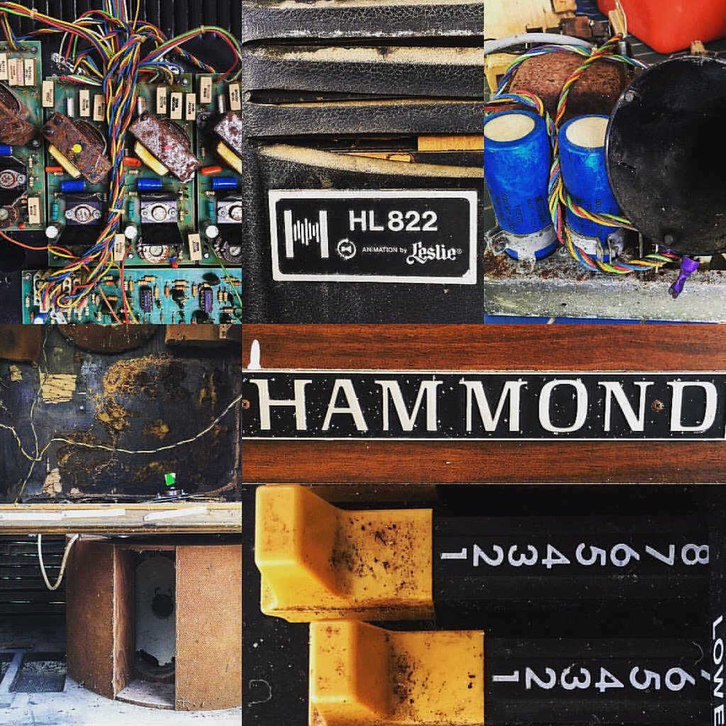
The comparison table below gives a one-page view across all four starter builds. Every factual cell is a placeholder until the corresponding record is completed.
16.1 Standard Restoration A
Cross-references: Vol 06 (death cap, safety, bench setup, moving and lifting) · Vol 07 (tonewheel generator oiling and service) · Vol 08 (AO-28 recap, B+ discharge, tube service) · Vol 09 (key contacts, busbar service, drawbars) · Vol 10 (vibrato scanner and run box) · Vol 11 (Leslie 122 service) · Vol 12 (cabinet restoration)
The standard restoration path takes a B-3, C-3, or A-100 console through the full service sequence in Part II of this bench manual and returns it to playing condition in its original cabinet. No modification; no chop. I use this path for any instrument where the cabinet is viable and the donor qualifies as a console worth preserving — the framework for that judgment is in Vol 13 §“The ethic: what to chop, what to spare,” which I apply before deciding on any instrument. The standard restoration keeps everything: the console shell, the legs, the bench, the original cabinet finish (or a sympathetic replacement). The only changes are the service interventions documented below.
16.1.1 The instrument
16.1.2 Why this build
16.1.3 Service work completed
The service sequence follows Part II of this bench manual in the order the volumes are laid out. All service work was completed on the open bench before the instrument was reassembled.
Death cap and mains safety (Vol 06 §“The AC death cap”):
Tonewheel generator service (Vol 07):
AO-28 recap and tube service (Vol 08):
Key contacts and drawbars (Vol 09):
Vibrato scanner (Vol 10):
Leslie 122 service (Vol 11):
Cabinet restoration (Vol 12):
16.1.4 Key parts and specifications
16.1.5 Result
16.2 Standard Restoration B
Cross-references: Vol 06 (death cap, safety, bench setup) · Vol 07 (tonewheel generator oiling and service) · Vol 08 (AO-28 recap, B+ discharge, tube service) · Vol 09 (key contacts, busbar service, drawbars) · Vol 10 (vibrato scanner and run box) · Vol 11 (Leslie 122 service) · Vol 12 (cabinet restoration)
The second standard restoration record. The same service path as Standard Restoration A — the full Part II sequence — applied to a different donor instrument with its own arrival condition, its own service history, and its own set of decisions. I keep a separate record for each instrument because the condition on arrival and the specific service interventions differ enough to matter: a generator that was bone-dry differs from one that was merely low on oil, and a console with active dendrite growth differs from one that cleaned up cleanly. The differences between records are what make the gallery useful as a long-term reference.
16.2.1 The instrument
16.2.2 Why this build
16.2.3 Service work completed
Death cap and mains safety (Vol 06 §“The AC death cap”):
Tonewheel generator service (Vol 07):
AO-28 recap and tube service (Vol 08):
Key contacts and drawbars (Vol 09):
Vibrato scanner (Vol 10):
Leslie 122 service (Vol 11):
Cabinet restoration (Vol 12):
16.2.4 Key parts and specifications
16.2.5 Result
16.3 Chop Build A
Cross-references: Vol 06 (death cap, safety, bench setup, moving and lifting) · Vol 07 (generator oiling — bench service before installation) · Vol 08 (AO-28 recap or combo preamp bench service) · Vol 09 (key contacts and drawbars — bench service before installation) · Vol 10 (vibrato scanner — bench service before installation) · Vol 11 (Leslie 122 service) · Vol 13 (chop planning and ethics: the five build decisions, weight budget, donor qualification) · Vol 14 (teardown sequence, harness labelling, portable enclosure fabrication) · Vol 15 (chop electronics: preamp wiring, start/run motor, Leslie switching, expression, grounding, first power-on)
The chop path extracts the working sub-assemblies from a donor console whose cabinet has failed or that is otherwise a legitimate chop candidate per Vol 13 §“The ethic: what to chop, what to spare” — the ethics framework I apply to every instrument before deciding to chop. The tonal sub-assemblies (tonewheel generator, manuals, preamp, vibrato scanner) move into a custom portable enclosure; the console shell, legs, and bench are left behind. The result is a multi-piece portable rig that can be transported to venues a 310 lb (141 kg) (est.) console cannot reach. The chop is electrically identical to the original console — no tonewheel capability is added or removed (Vol 13 §“What chopping means”) — and it is irreversible once the console shell is discarded. I treat that irreversibility seriously: the record below documents the specific conditions that justified this build.
16.3.1 The instrument
16.3.2 Why this build
16.3.3 Sub-assembly extraction (Vol 14)
The teardown sequence followed the Vol 14 extraction order — safety gate first, then harness inventory and photo-and-label gate before any connector was disconnected, then scanner, AO-28, manuals, and generator in that order. The harness labelling protocol in Vol 14 §“Photographing and labelling” is the most critical step: every connector received masking-tape flags on both the cable side and the socket side, photographed together in the same frame, before disconnection. A mis-connected foldback harness (Vol 09 §“The key-contact matrix and foldback”) produces wrong notes that are nearly impossible to diagnose from outside a completed enclosure.
16.3.4 Sub-assembly service — bench work before installation (Vols 07–10)
All sub-assemblies were serviced on the open bench before installation in the new enclosure, per Vol 13 §“Gate 4: Service work planned.” Servicing a sub-assembly inside a completed portable enclosure is far harder than servicing it on the bench — this sequence is not optional.
Tonewheel generator service (Vol 07):
AO-28 recap and tube service (Vol 08) — if original AO-28 retained:
Key contacts and drawbars (Vol 09):
Vibrato scanner (Vol 10) — if original scanner retained:
Leslie 122 service (Vol 11):
16.3.5 Enclosure fabrication (Vol 14)
The portable enclosure was built to the measured dimensions of the specific extracted sub-assemblies, per Vol 14 §“Designing the portable cabinet.” Community-range estimates from Vol 14 were used only as a starting point; every cutting dimension was derived from measuring the actual extracted manuals, generator case, and AO-28 chassis.
16.3.6 Chop electronics (Vol 15)
With the sub-assemblies mechanically installed, the wiring followed Vol 15 in the documented order: preamp wiring, then the start/run motor power sequence, then Leslie output and half-moon switching, then expression, then the grounding scheme, then the bench-test procedure for first power-on.
16.3.7 Key parts and specifications
16.3.8 Result
16.4 Chop Build B
Cross-references: Vol 06 (death cap, safety, bench setup) · Vol 07 (generator oiling — before installation) · Vol 08 (AO-28 recap or combo preamp) · Vol 09 (key contacts and drawbars — before installation) · Vol 10 (vibrato scanner — before installation) · Vol 11 (Leslie 122 service) · Vol 13 (chop planning: ethics, five build decisions, weight budget) · Vol 14 (teardown, harness labelling, enclosure fabrication) · Vol 15 (chop electronics: preamp, start/run motor, Leslie switching, expression, grounding)
The second chop build follows the same path as Chop Build A — extraction per Vol 14, bench service per Vols 07–10, enclosure fabrication per Vol 14, and chop electronics per Vol 15 — applied to a different donor instrument with a different set of build decisions and a distinct outcome. I keep separate records because the details diverge: a different donor model brings different sub-assembly geometry; a different preamp choice brings a different wiring path; a different enclosure configuration brings different piece weights and load-in behaviour. The differences between Chop Build A and Chop Build B are as informative as the records individually.
16.4.1 The instrument
16.4.2 Why this build
16.4.3 Sub-assembly extraction (Vol 14)
16.4.4 Sub-assembly service — bench work before installation (Vols 07–10)
Tonewheel generator service (Vol 07):
AO-28 recap or combo preamp (Vol 08 or Vol 15):
Key contacts and drawbars (Vol 09):
Vibrato scanner (Vol 10):
Leslie 122 service (Vol 11):
16.4.5 Enclosure fabrication (Vol 14)
16.4.6 Chop electronics (Vol 15)
16.4.7 Key parts and specifications
16.4.8 Result
Cross-references across the 18-volume arc: Vol 01 (B-3 overview and the Hammond console lineage, 1954–1975) · Vol 02 (theory of operation: tonewheel generator, drawbar additive synthesis, key-contact matrix, foldback, AO-28 signal path) · Vol 03 (controls and operation: drawbar registration, percussion, vibrato and chorus, expression) · Vol 04 (Leslie 122: rotary theory, 6-pin Amphenol interface, tube amplifier, 800 Hz crossover, horn and drum rotors) · Vol 05 (bass: 25-note pedalboard, tonewheel pedal tone, Trek II bass expander) · Vol 06 (tools, bench setup, death cap removal, B+ discharge procedure, moving and lifting a console) · Vol 07 (tonewheel generator oiling, shunt-cap service, dead-note triage) · Vol 08 (AO-28 recap, B+ power supply, tube service, percussion circuit) · Vol 09 (manual key contacts, the busbar and dendrites, drawbar service, manual R&R, foldback wiring) · Vol 10 (vibrato scanner and run box: the mechanical scanner, run motor, line box, service procedure) · Vol 11 (Leslie 122 service: 6550 tube amp recap, rotor motors, belts, bearings, crossover, level set) · Vol 12 (standard cabinet restoration: condition assessment, refinishing, veneer, hardware, the “keep it original” ethic) · Vol 13 (chopping a B-3: the ethics and donor-qualification framework, the five build decisions, weight and piece budget, chop project checklist) · Vol 14 (the chop: teardown sequence, harness labelling, generator extraction, portable enclosure design and fabrication) · Vol 15 (chop electronics: preamp wiring, start/run motor power, Leslie output and half-moon switching, expression, grounding, first power-on) · Vol 17 (recording and studio integration: mic’ing the Leslie, levels, interfacing, MIDI, studio signal chain) · Vol 18 (reference cheatsheet: tonewheel frequency table, drawbar registration chart, specification tables, bibliography).
Comments (0)